Axial flow pump with mult-grooved rotor

a rotor and axial flow technology, applied in the field of rotary pumps, can solve the problems of reducing the torque capacity and efficiency of the motor, and achieve the effects of improving the output flow characteristics of the blood, improving the resistance to thrombosis, and simple mechanical design

Inactive Publication Date: 2007-05-03
HEARTWARE INC
View PDF99 Cites 94 Cited by
  • Summary
  • Abstract
  • Description
  • Claims
  • Application Information

AI Technical Summary

Benefits of technology

[0011] A plurality of hydrodynamic thrust bearing surfaces is provided on each of the peripheral surfaces of the land areas of the rotor. The bearing surfaces create fluid pressure at the periphery of the rotor thereby imparting radially symmetrical forces to the rotor, which maintain the radial position of the rotor within the housing when the rotor is spinning, and to provide good washing near the surrounding housing for increased resistance to thrombosis.
[0018] In some embodiments, a volute may be used at the output end of the housing to improve the output flow characteristics of the blood. For example, a volute may be used to redirect the blood flow in a direction normal to the rotational axis of the pump. A volute may improve the output blood flow characteristics of an axial flow pump by converting rotational kinetic energy in the output flow from the axial flow pump to a slower output velocity having sufficient pressure for discharge into the vascular system.

Problems solved by technology

Both of these approaches tend to reduce the motor torque capacity and efficiency, and they require mechanical rotor support involving abutting surfaces that move and wear against each other in rotation.

Method used


Image

  • Axial flow pump with mult-grooved rotor
  • Axial flow pump with mult-grooved rotor
  • Axial flow pump with mult-grooved rotor

Examples


Embodiment Construction

[0052] In describing the preferred embodiments of the present disclosure illustrated in the drawings, specific terminology is employed for sake of clarity. However, the present disclosure is not intended to be limited to the specific terminology so selected, and it is to be understood that each specific element includes all technical equivalents which operate in a similar manner.

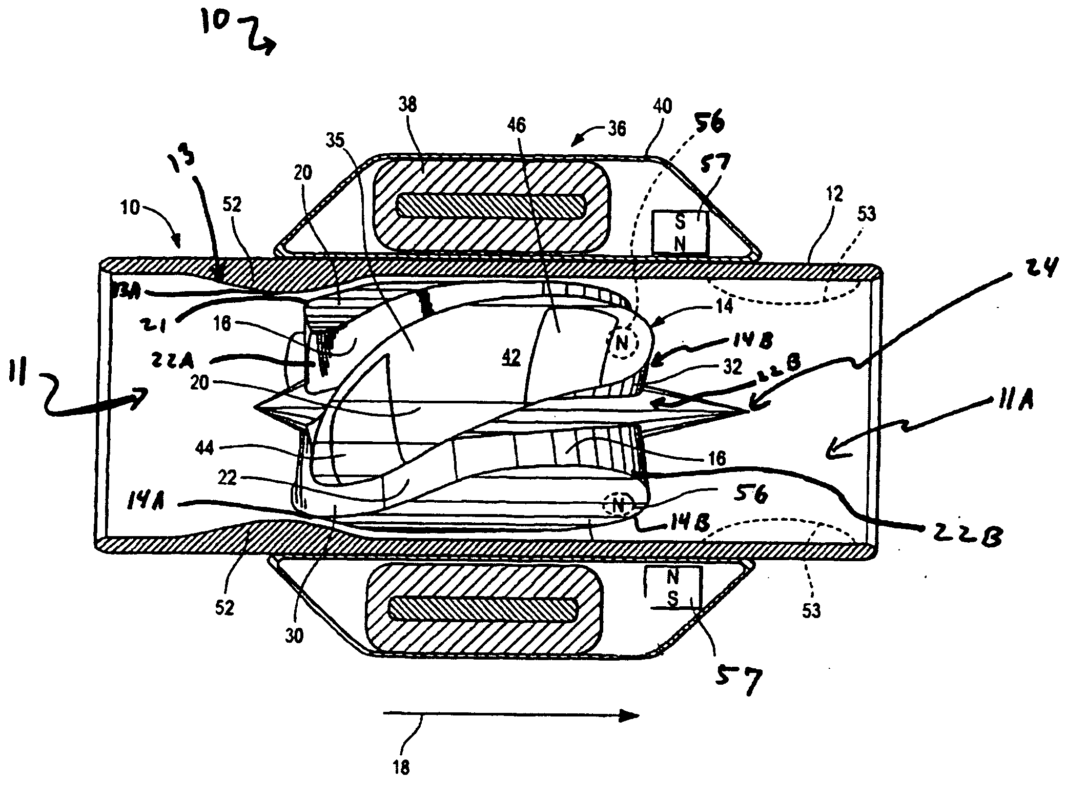
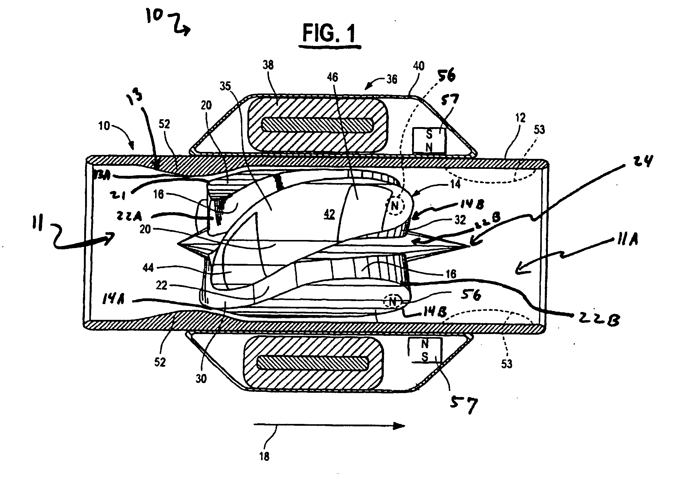
[0053] Referring now to the drawings and in particular to FIGS. 1-5, an embodiment of a blood pump 10 adapted to assist in pumping blood through a patient's vascular system is disclosed, comprising a hollow generally tubular pump housing 12. The pump housing 12 is non-magnetic and is made of a suitable biocompatible material such as titanium or a suitable ceramic material which is non-thrombogenic, rigid and exhibits minimum eddy current lossess. The housing 12 defines a blood inlet end 11 and a blood outlet end 11A so that blood flows through the housing in the direction shown by the arrow 18. In one embod...


PUM


Abstract

An axial-flow blood pump for pumping blood includes a substantially cylindrical outer enclosure. A tubular housing concentric with and located within the outer enclosure has at one end an inlet and at an opposite end an outlet. A motor stator is concentric with and located between the outer enclosure and the tubular housing. An impeller is concentric with and located within the tubular housing. The impeller is suspended in operation by a combination of passive magnetic forces between magnets within the impeller or magnetized regions of the impeller and the motor stator and hydrodynamic thrust forces generated as blood flows between the tubular housing and a plurality of hydrodynamic thrust bearing surfaces located on the impeller. A volute may be in fluid-tight connection with the outlet of the tubular housing for receiving blood in the axial direction and directing blood in a direction normal to the axial direction. The volute has a flow-improving member extending axially from the volute and into and coaxially with the tubular housing.

Description

REFERENCE TO RELATED APPLICATIONS [0001] The present application is a continuation-in-part of: U.S. application Ser. No. 11 / 003,810, filed Dec. 3, 2004; PCT International Application No. PCT / US2005 / 042495, filed Nov. 22, 2005; U.S. application Ser. No. 11 / 118,551 filed Apr. 29, 2005; PCT International Application No. PCT / US2005 / 035964, filed Oct. 6, 2005; and U.S. application Ser. No. 11 / 243,722, filed Oct. 5, 2005. The contents of each of the foregoing applications is hereby incorporated herein by reference.FIELD OF THE INVENTION [0002] The present disclosure relates to rotary pumps and, in particular, to axial flow blood pumps having a generally cylindrical rotor suspended within a corresponding cylindrical housing having a blood inlet at one end and blood outlet at another end, and motor components to provide rotational energy to spin the rotor and pump blood fluid longitudinally through the housing from the housing inlet to the housing outlet. BACKGROUND OF THE INVENTION [0003] ...

Claims


Application Information

Patent Timeline
Patent Type & Authority Applications(United States)
IPC IPC(8): A61M1/12A61M60/196A61M60/237A61M60/422A61M60/508A61M60/806A61M60/81A61M60/82A61M60/824
CPCA61M1/101A61M1/1015A61M1/1017A61M1/1031A61M1/125A61M1/1008A61M1/1029A61M1/1036A61M1/122A61M60/824A61M60/82A61M60/422A61M60/148A61M60/81A61M60/508A61M60/806A61M60/237A61M60/196F04D3/02A61M60/419F04D29/0476
Inventor LAROSE, JEFFREY A.SHAMBAUGH, CHARLES R. JR.TRICHI, KARTIKEYANMARQUIS, RICHARD A.WHITE, DANIEL G.
Owner HEARTWARE INC
Why Eureka
Try Eureka