
Interface for a database for a field unit

Inactive Publication Date: 2007-05-03
VEGA GRIESHABER GMBH & CO
View PDF18 Cites 6 Cited by
  • Summary
  • Abstract
  • Description
  • Claims
  • Application Information

AI Technical Summary

Benefits of technology

[0019] By using a measurement value logging system, reliable or fault-tolerant transmission of information between communication module and database may be achieved.
[0039] According to another exemplary embodiment of the present invention, a database is provided, wherein the interface of the database is written in a script language. By writing the interface in a script language it may be possible to flexibly adapt the communication with a communication module to possibly newly appearing demands. For example, it might be necessary for the storing to store new or other parameters of measurement values, whereby the information to be transmitted between communication module and database would have to be extended. By a higher level layer of an interface, written in a script language, it may be possible to respond to changes or new demands when transmitting measurement values.

Problems solved by technology

However, with such polling procedures, or with fetching procedures triggered by the user, it is rather difficult to fetch information immediately after it has been logged.
Especially with irregular measurement value logging, it may happen that the time interval between interrogation and provision of a measurement value is very long.
Or it may happen that interrogation is done in intervals that are too short so that the measuring system is additionally loaded with frequent interrogation and performance thereof is impaired.

Method used


Image

  • Interface for a database for a field unit
  • Interface for a database for a field unit
  • Interface for a database for a field unit

Examples


Embodiment Construction

[0053] Illustrations in the figures are schematic and not to scale. In the following description of FIGS. 1 to FIG. 10, the same reference signs are used for like or corresponding elements.

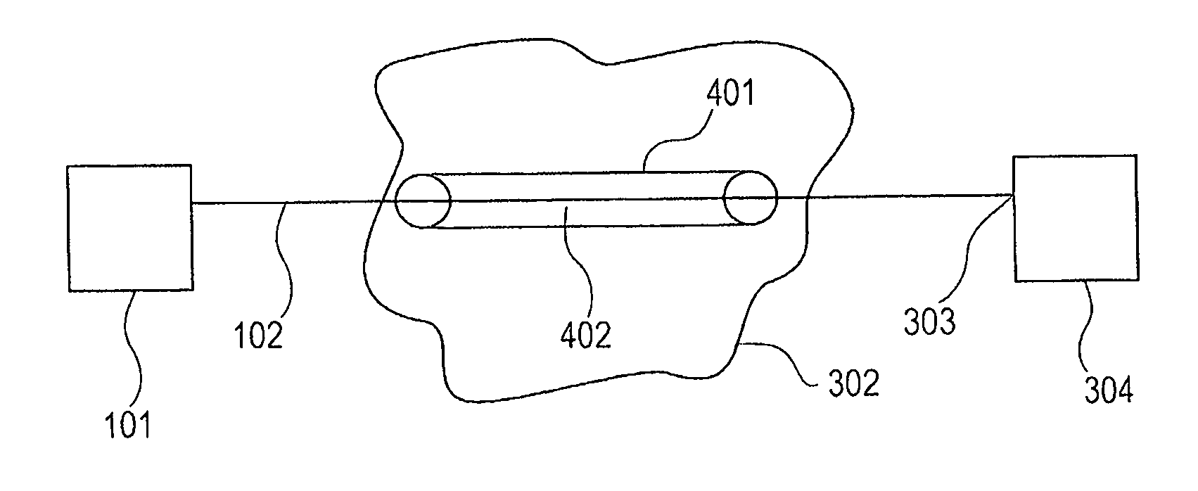
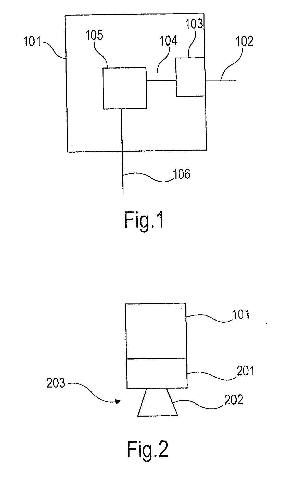
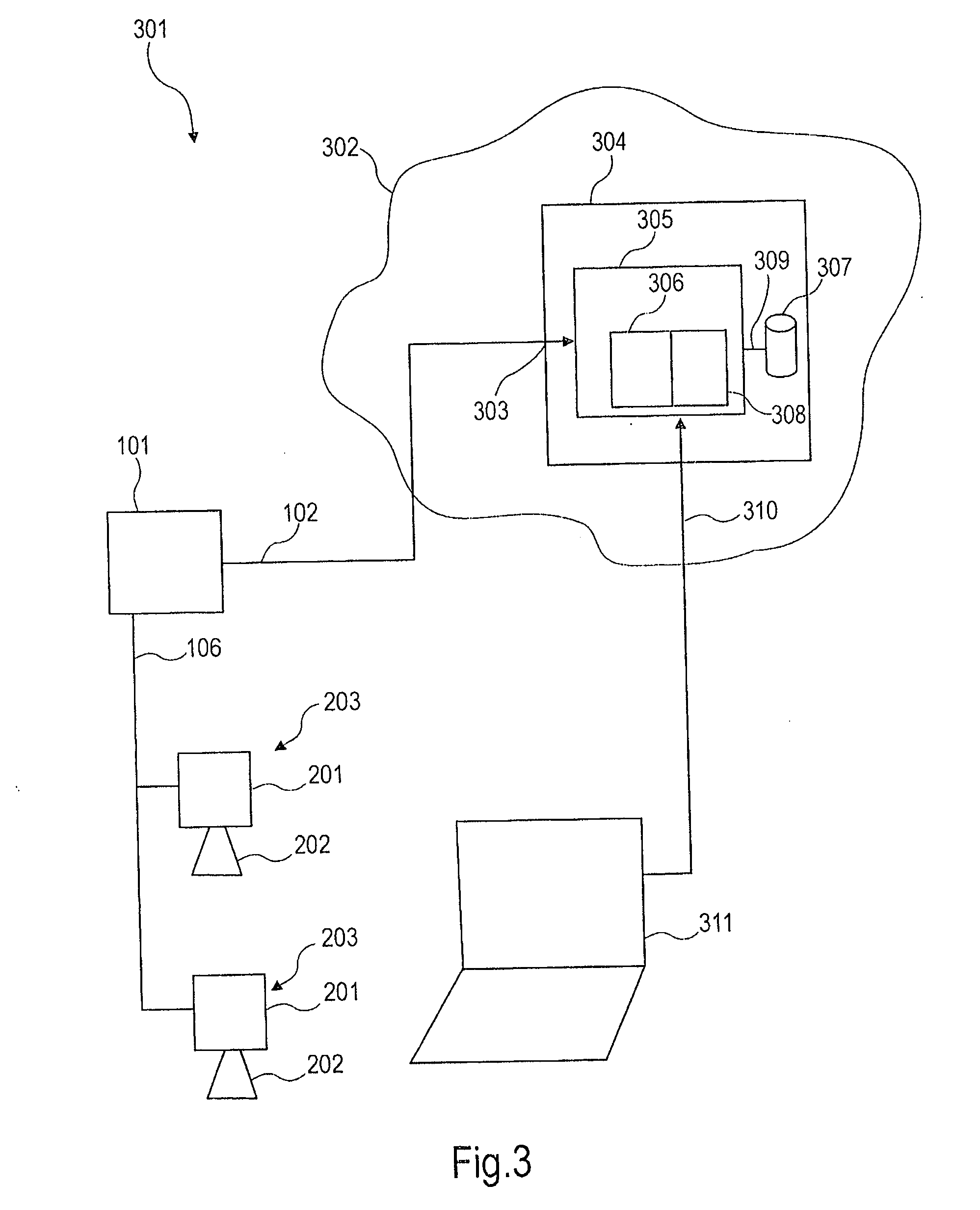
[0054]FIG. 1 shows a functional diagram of a communication module according to an exemplary embodiment of the present invention. The communication module 101 comprises a measurement value processing device 105 and a web client 103. The measurement value processing device 105 is connectable to a measuring instrument via a first interface 106. For this purpose, the first interface 106 is e.g. a bus protocol, such as I2C, HART®, Profibus, Fieldbus Foundation™, or VEGA VBUS. Thus, via the first interface 106 a connection to any measuring instrument, which has a corresponding bus, can be set up.

[0055] The measuring instrument can be arranged remote from the communication module 101, and consequently is not represented in FIG. 1. Communication between communication module 101 and a measuring instrumen...


PUM


Abstract

A communication module for a measuring instrument may include a first interface, a second interface, and an integrated web client. To the first interface a measuring instrument can be connected, whereas to the second interface a database can be connected. The communication module is configured to receive at the first interface a measurement value and to forward it to the second interface by the web client.

Description

PRIORITY CLAIM [0001] This application claims the benefit of the filing date of U.S. Provisional Patent Application No. 60 / 730,713 filed Oct. 27, 2005 and of German Patent Application No. 10 2005 051 580.0 filed Oct. 27, 2005, the disclosures of which are hereby incorporated herein by reference.FIELD OF THE INVENTION [0002] The present invention relates in general to the technical field of metrology. In particular, the present invention relates to a communication module for a measuring instrument, a database, a measurement value logging system, a method for processing measurement values, and a measuring instrument assembly. TECHNOLOGICAL BACKGROUND [0003] When logging measurement values it is very often decisive to relate measurement values of various process quantities in order to obtain evaluations based thereon. In this case, it happens frequently that measurement values have to be picked up at different locations, which are often spaced very far apart, and have to be transferred...

Claims


Application Information

Patent Timeline
IPC IPC(8): G06F15/173
CPCG01F15/063G01F23/0069G05B19/0423G05B2219/25204G05B2219/25217H04L67/02G05B2219/34039G06F17/30893H04Q9/00H04L67/125G05B2219/25428G06F16/972G01F23/802
Inventor ISENMANN, ANDREASFAIST, FRIDOLINSCHAETZLE, RALF
Owner VEGA GRIESHABER GMBH & CO
Features
  • Generate Ideas
  • Intellectual Property
  • Life Sciences
  • Materials
  • Tech Scout
  • Unparalleled Data Quality
  • Higher Quality Content
  • 60% Fewer Hallucinations
Learn More