
Modular planter system

a planter system and modular technology, applied in the field of modular planter systems, can solve the problems of not being able to meet the needs of planters, planters or modular devices for vegetative cover on terraces, balconies, decks or roofs, and the use of systems or individual containers, etc., to reduce the saturated weight load, reduce heat island effects, and increase water retention

Inactive Publication Date: 2007-05-10
LICHT JEFF L
View PDF23 Cites 28 Cited by
  • Summary
  • Abstract
  • Description
  • Claims
  • Application Information

AI Technical Summary

Benefits of technology

[0019] The general aim of the current invention was to reduce saturated weight loads, increase water retention, reduce heat island effects, increase mobility, enhance ease of use, increase ecological benefits, simplify irrigation and enhance permeable access pathways for recreation, maintenance and repair.
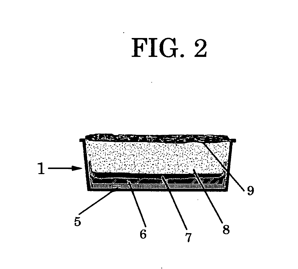
[0021] The most important specific benefits derived from the current invention include: (1) portability and mobility of a strong, lightweight frame, (2) superior water retention, root and soil infiltration retardation afforded by the use of two novel geotextiles, (3) customized soil depths in graduated planters using polypropylene copolymer inserts, (4) lower saturated weights from proprietary soil blends, and (4) greater substrate water retention over a longer period of time. Other benefits are described as well.

Problems solved by technology

Briefly, there is nothing new about the use of systems or individual containers, planters or modular devices for vegetative cover on courtyards, terraces, balconies, decks or roofs.
However, modular systems are typically heavy and difficult to move in a saturated condition.
The problem until now has been the monolithic—linear rectangles—aspects of modular design.
Heretofore, somewhat elaborate and complicated irrigation had been made available.
Modular systems have not been designed specifically to address ballast and aerodynamic properties which come into play in high wind situations, nor the need to balance these concerns with portability and ease of mobility.

Method used


Image

  • Modular planter system
  • Modular planter system
  • Modular planter system

Examples


Embodiment Construction

[0043] Detailed description of modular planter system The present invention relates to both terrestrial and roof applications of a modular planter system. The system combines existing products and their functionalities in new ways to achieve superior benefits described in the foregoing sections.

[0044] Previously, green roof modular panels (such as those described in U.S. Pat. No. 6,711,851 and U.S. Pat. No. 6,862,842) have been used for application to “green” roofs. While concerns for the water holding function for plant growth were addressed, other significant benefits regarding the maximization of storm water retention and atmospheric redistribution were not. The utilitarian approach taken by the former art which failed to account for the sometimes nuanced relations between root systems, water transport and retention, compaction, and ecological balance achieved with mimicry of vegetative stories—over, middle and under—to afford better plant survival. By using fabrics and plastics...


PUM


Abstract

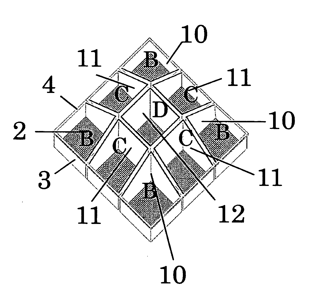
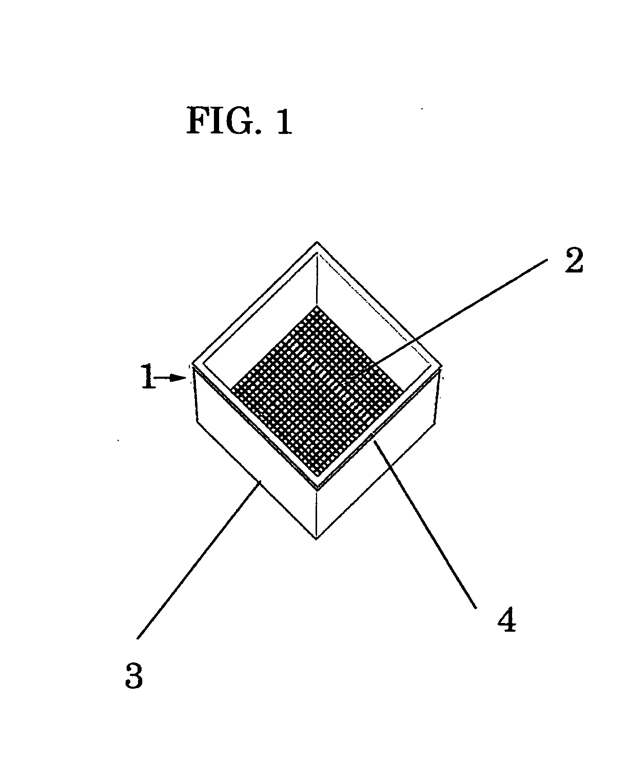
A modular planter system is comprised of high density polyethylene plastic propagation flats, geotextile fabrics, plastic inserts, soil capable of supporting plant, shrub and tree growth, and plants for use on impermeable surfaces. The planter system comprises four similarly constructed units with progressively deeper soil depths achieved through the use of plastic inserts and grouped according to a pre-arranged design. More particularly the planter system is comprised of modules each with its own blended soil, plant material, soil, root retardant, and water retentive non-woven geotextile and inserts. Planters are not connected but installed side by side. Each planter may be moved from its place without having to move other planters. Planter units are assembled ahead of use and transported to the installation site on wooden palettes or via similar conveyance. The planter system can be used with or without edging, and has optional apparati including irrigation and walkable functionalities.

Description

CROSS-REFERENCES TO RELATED APPLICATIONS [0001] This application claims the benefit of U.S. Provisional Patent Application Ser. No. 60 / 734,140 filed Nov. 7, 2005, U.S. Provisional Patent Application Ser. No. 60 / 781,779 filed Mar. 13, 2006 and U.S. Provisional Patent Application Ser. No. 60 / 781,922 filed Mar. 13, 2006, the disclosures of which are incorporated hereinto by reference.REFERENCE TO MICROFICHE APPENDIX [0002] Not applicable. STATEMENT REGARDING FEDERALLY SPONSORED RESEARCH OR DEVELOPMENT [0003] Not applicable. TECHNICAL FIELD [0004] The present invention relates generally to a plurality of portable, non-interlocking modular planter systems used to support vegetation on impermeable and permeable surfaces. More particularly, the present invention relates to a planter system comprising four similar types of non-interlocking units, methods, research, and apparatus for use thereof. BACKGROUND OF THE INVENTION [0005] Briefly, there is nothing new about the use of systems or ind...

Claims


Application Information

Patent Timeline
IPC IPC(8): A01G9/02
CPCA01G9/02A01G1/007A01G9/033
Inventor LICHT, JEFF L.
Owner LICHT JEFF L
Learn More