
Method and device for mounting a rotating member

a rotating member and mounting method technology, applied in the field of sources, can solve the problems of inability to meet the needs of production, noisy vibration, imbalances that contribute to the vibration of the entire tube,

Inactive Publication Date: 2007-05-10
GENERAL ELECTRIC CO
View PDF21 Cites 2 Cited by
  • Summary
  • Abstract
  • Description
  • Claims
  • Application Information

AI Technical Summary

Benefits of technology

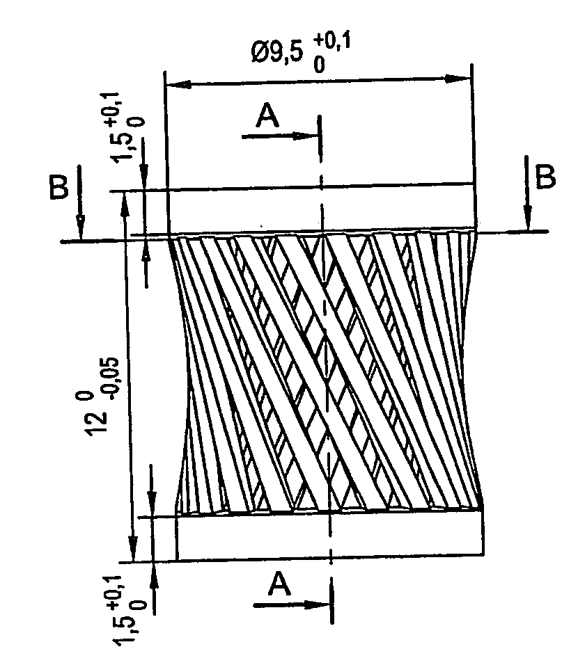
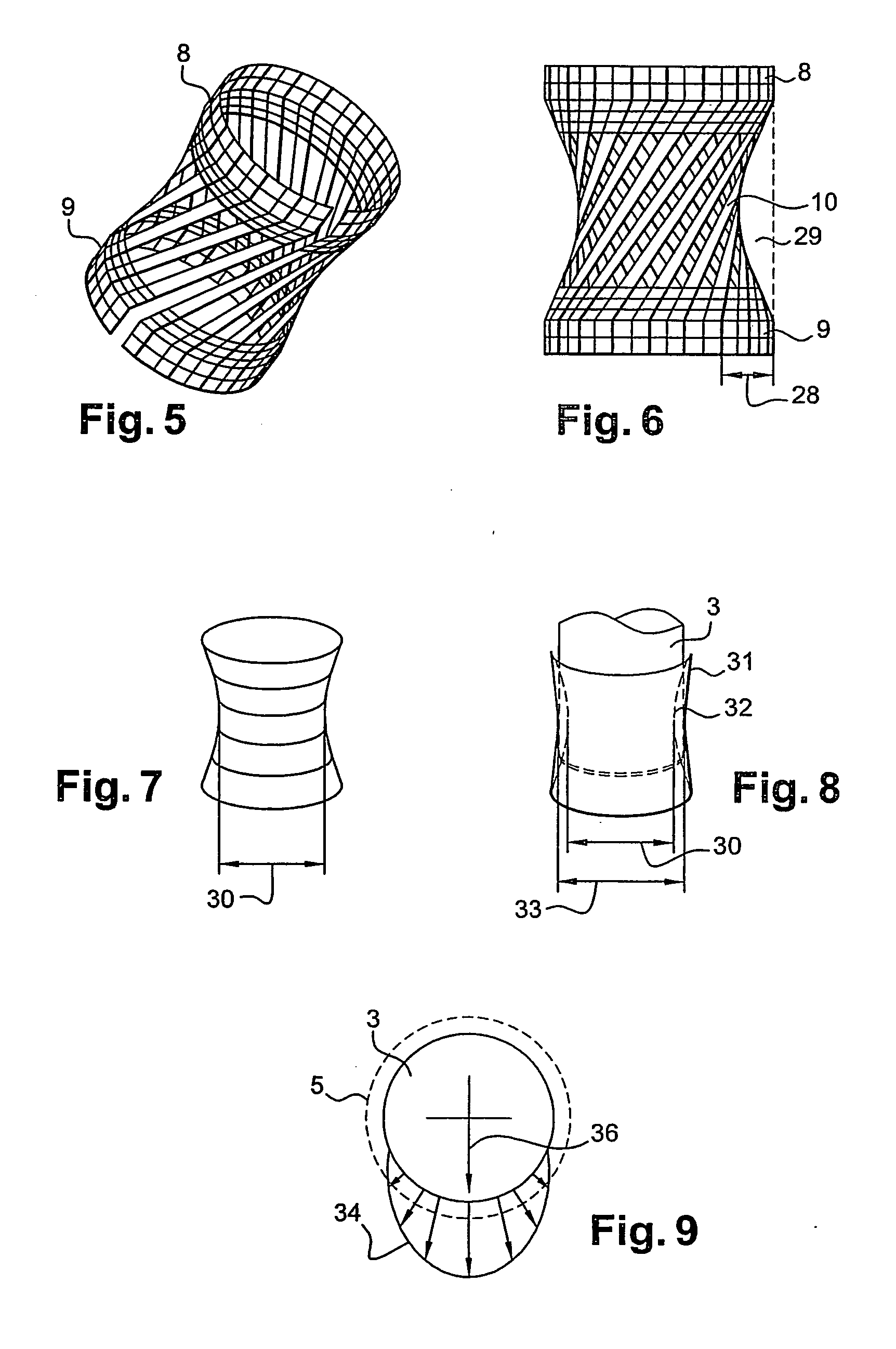
[0006] An embodiment of the invention is directed to a method for making the diabolo-shaped rings so that the cost of their manufacture is reduced to the minimum. In an embodiment of the method, the diabolo shape is a hyperboloid shape.

Problems solved by technology

These vibrations are noisy.
Despite all the efforts made to balance this rotating part, there are imbalances that contribute to making the entire tube vibrate.
If the linking of the structures is rigid, such an assembly leads to a hyperstatic condition in the holding of the shaft and, at a mechanical level, it entails breaks that are unacceptable.
The rings used, which generally have a squirrel-cage shape, are elastic but have the drawback of not being reusable.
Indeed, the rings are deformed because they have to be force-fitted when mounted in a structure, before the insertion of a shaft end.
Furthermore, the insertion of the rings themselves requires an exertion of considerable force during assembly.

Method used


Image

  • Method and device for mounting a rotating member
  • Method and device for mounting a rotating member
  • Method and device for mounting a rotating member

Examples


Embodiment Construction

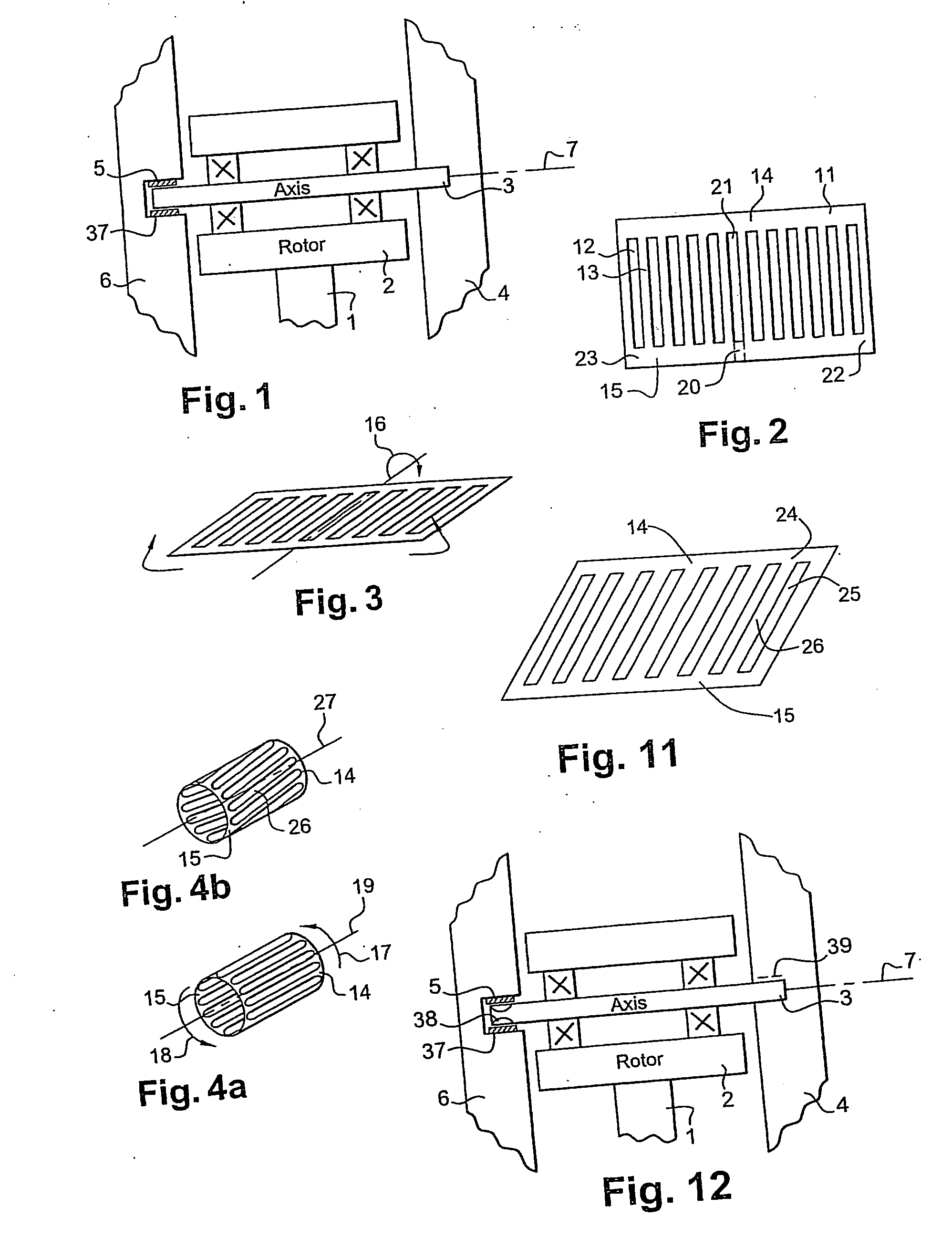
[0016]FIG. 1 shows a device for mounting a rotating member such as an anode 1 in an X-ray tube. The X-ray tube itself is not shown. The rotating anode 1 is thus rigidly mounted on a motor-driven rotor (preferably a brushless electric motor) about a shaft 3. The shaft 3 is mounted, for example rigidly, in a first fixed structure 4 and by means of the ring 5, in a second structure 6. A rotor 2 and the rotating anode 1 rotate about an axis of rotation 7 aligned with the shaft 3. In this example, the shaft 3 is rigidly fixed to the structure 4 by known means. For example, it is screwed into the structure with a screw. The structures 4 and 6 are furthermore connected in the sheathing of the X-ray tube so that they are fixed with respect to each other. In practice, one of the two structures, in this case the structure 4, is massive. The other structure, namely the structure 6, is lighter. In any case, the structure 4 is less sensitive than the structure 6 to the vibratory forces generatin...


PUM


Abstract

A rotating anode is mounted on a shaft of an X-ray tube by means of a ring. The ring allows expansion and reduces the hyperstatic state of the assembly. The ring has the shape of a diabolo, preferably that of a hyperboloid structure generated by revolution. The ring dampens vibration phenomena in a shaft bearing the rotating anode and reduces noise-creating phenomena.

Description

CROSS-REFERENCE TO RELATED APPLICATIONS [0001] This application is a divisional application of U.S. application Ser. No. 10 / 825,512 filed Apr. 15, 2004, which is hereby incorporated by reference in its entirety, and claims the benefit of a priority under 35 USC 119(a)-(d) to French Patent Application No. 03 50113 filed Apr. 17, 2003, the entire contents of which are hereby incorporate by reference.BACKGROUND OF THE INVENTION [0002] The present invention is directed to a method and a device for mounting a rotating member. In particular, the present invention is directed to a source of radiation and, more particularly the mounting of a rotating anode in an X-ray tube and a method for manufacturing a part of this device. The rotating anode tubes are X-ray emitting tubes used mainly in mammography, although their use can be envisaged in other fields of radiology, especially tomodensitometry. In mammography, the conditions of the examination require the patient to place his or her breast...

Claims


Application Information

Patent Timeline
Patent Type & Authority Applications(United States)
IPC IPC(8): B21D43/28F16F15/06F16C13/00F16C13/02H01J35/10
CPCH01J35/101Y10T403/7061H01J2235/1053H01J2235/1046H01J9/18F16C17/02F16C27/02
Inventor LACHERADE, XAVIER ARMANDLE-PIERRARD, CAROLINEJOSSE, JEAN-LUC
Owner GENERAL ELECTRIC CO
Learn More