Loop impedance meter

a technology of impedance meters and loops, applied in the direction of resistance/reactance/impedence, impedence measurements, instruments, etc., can solve the problems of phase and neutral currents not being balanced, supply out of service, generally inconvenient, etc., to reduce the time constant of the circuit, reduce the settling time, and reduce the effect of test curren

Inactive Publication Date: 2007-05-10
MARTINDALE ELECTRIC
View PDF3 Cites 47 Cited by
  • Summary
  • Abstract
  • Description
  • Claims
  • Application Information

AI Technical Summary

Benefits of technology

[0009] By increasing the load resistance, the time constant of the circuit is decreased. Further, the test current is also decreased, and we have observed that typical conventional RCDs can tolerate levels of current flow in inverse proportion to the duration of the current pulse. Typically, an RCD can take the current

Problems solved by technology

The phase-earth loop impedance measurement inherently has a current flow from phase to earth and hence the phase and neutral currents cannot be balanced.
The problem here is that conventional loop impedance meters for measuring the phase-earth loop impedance tend to trip the RCD, which puts the supply out of service until the RCD can be reset.
This prevents any repeat of the loop impedance measurement until the RCD has been reset, and it is also generally inconvenient.
This very large earth current for this length of time will trip the RCDs in the circuit, which is very inconvenient w

Method used


Image

  • Loop impedance meter
  • Loop impedance meter
  • Loop impedance meter

Examples


Embodiment Construction

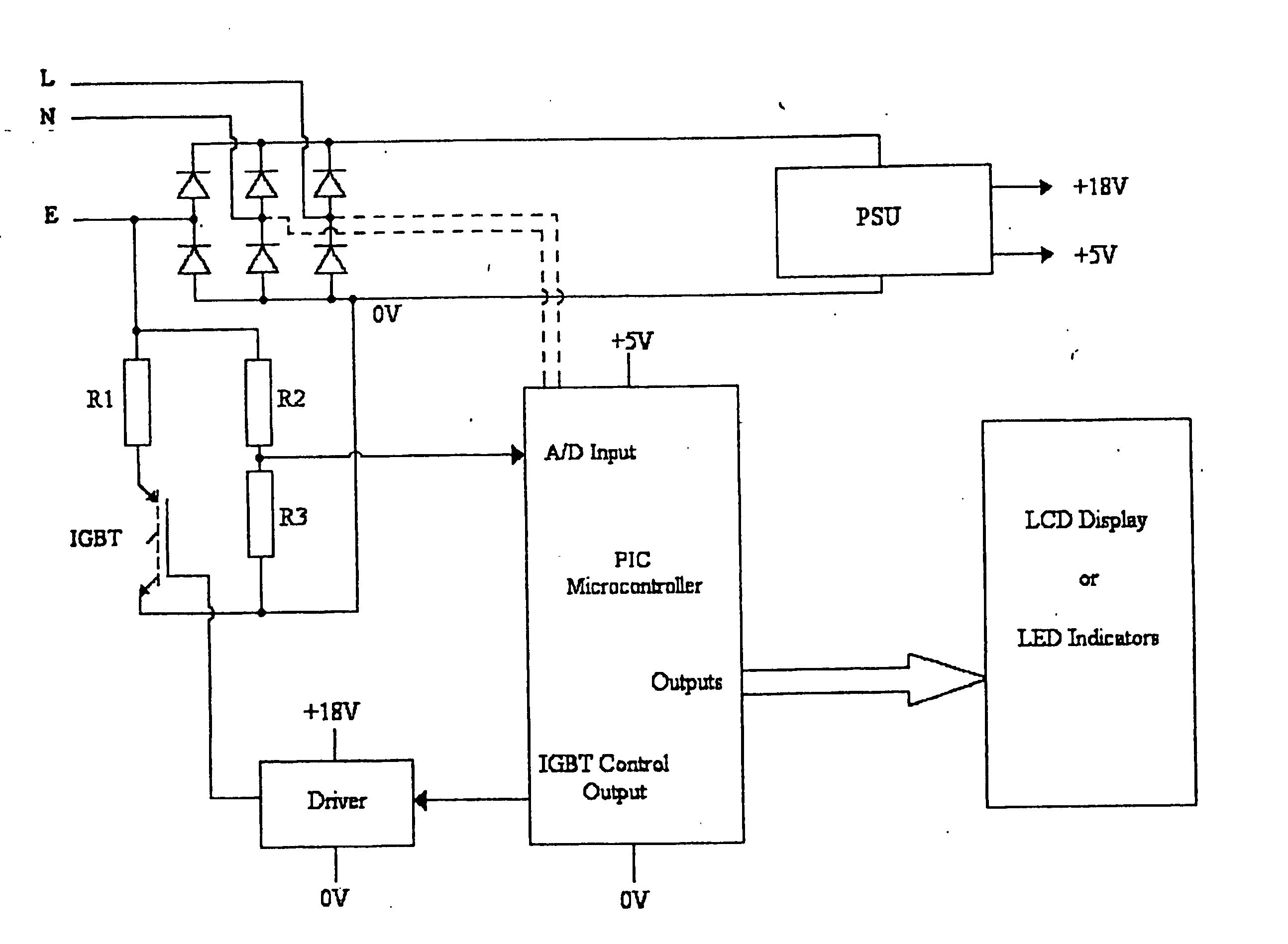
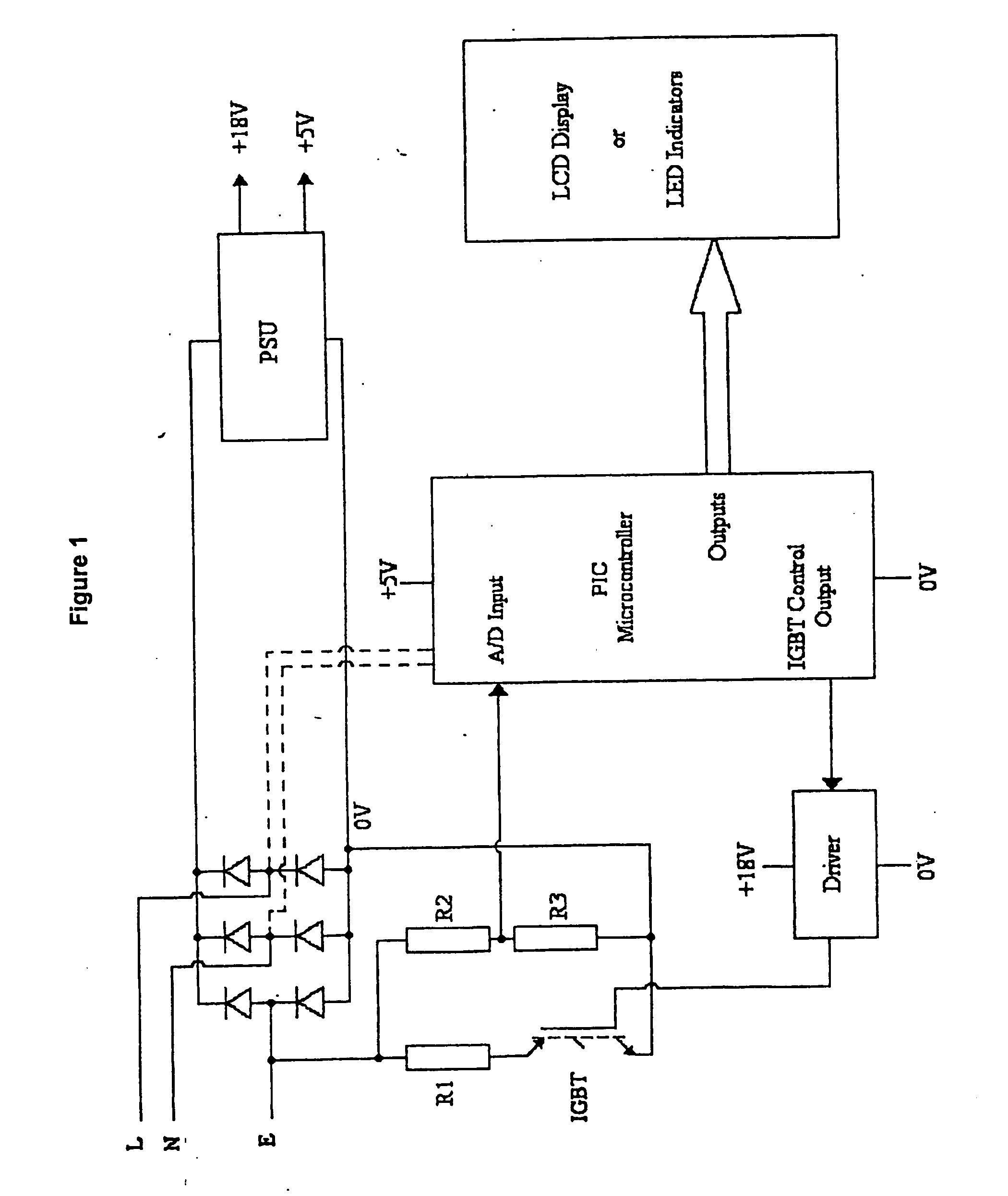
[0031] A loop impedance meter whose schematic circuit diagram is shown in FIG. 1 comprises a housing connectable to a typical A.C. mains supply, and a display for providing an indication of loop impedance. In a first example, for use typically by a non-specialist, the housing has pins for insertion into a typical mains socket, and a display comprising an array of light emitting diodes (LEDs). In a preferred embodiment, there are three indicators which each glow either green or red, the combined display indicating the impedance in one of six ranges. In this example, the ranges are 0 to 1.7 ohms; 1.7 to 5 ohms; 5 to 10 ohms; 10 to 50 ohms; 50 to 100 ohms and 100 to 500 ohms.

[0032] In an alternative embodiment of the invention, the housing instead has a liquid crystal display (LCD) giving a numerical readout of impedance. In another embodiment of the invention, Instead of using pins for insertion into a mains socket, adaptors and crocodile clips are provided instead.

[0033] In each ca...


PUM


Abstract

A loop impedance meter is provided for testing an A.C. electrical mains supply. The meter comprises an electronic control circuit for connecting a load resistance intermittently between the A.C. mains supply terminal and the earth terminal to measure the potential difference between those terminals and to provide an indication of the loop impedance of the A.C. mains supply from that potential difference. The control circuit is arranged to allow a train of short pulses of current to flow through the load resistance and the loop, the pulse train beginning its sequence with a first train of pulses for preconditioning any residual current device-present in the loop to temporarily desensitize it. The first train of pulses is followed by one or more measurement pulses, the pulses of the first train being of generally increasing width.

Description

CROSS-REFERENCE TO RELATED APPLICATIONS [0001] Not Applicable STATEMENT RE: FEDERALLY SPONSORED RESEARCH / DEVELOPMENT [0002] Not Applicable [0003] This invention relates to a loop impedance meter for testing alternating current (A.C.) electrical mains supplies; and to a method of using it. BACKGROUND [0004] Loop impedance meters are used to measure the impedance of the phase-earth circuit. This is done to ensure that, under a fault condition, the resultant current will be large enough to trip the circuit breaker or to blow the supply fuse. Many modern installations have an additional safety device known as a residual current device (RCD). RCDs effectively compare the current flowing in the phase and neutral circuits, and, if the current to earth should exceed a preset value, disconnect the supply. The phase-earth loop impedance measurement inherently has a current flow from phase to earth and hence the phase and neutral currents cannot be balanced. The problem here is that convention...

Claims


Application Information

Patent Timeline
IPC IPC(8): G01R31/08
CPCG01R27/16
Inventor BATTEN, DOUGLAS WILLIAMGORDON, MARTIN IAN
Owner MARTINDALE ELECTRIC
Why Eureka
Try Eureka