Auto-aligning and connecting structure between electronic device and accessory

a technology of connecting structure and electronic device, which is applied in the direction of magnet bodies, instruments, snap-action arrangements, etc., can solve the problems of inability to meet the connectivity and alignment needs of modern electronic devices and their associated accessories, the connector is too complicated to manufacture, and the connector is too large, etc., to achieve convenient fabrication and facilitate connection

Active Publication Date: 2007-05-10
HTC CORP
View PDF16 Cites 116 Cited by
  • Summary
  • Abstract
  • Description
  • Claims
  • Application Information

AI Technical Summary

Benefits of technology

[0011] The present invention provides an auto-aligning and connecting structure that facilitates the connection between an electronic device and an accessory. The structure is small, light, easy to fabricate, sturdy, and it allows users to connect and disconnect accessories from electronic devices in a quick and proper manner.
[0013] In the foregoing, it is seen that the mutual attraction between the first magnetic units and the second magnetic units facilitates the alignment and connection between the electronic device and its accessory.
[0014] In conclusion, the invention facilitates the connection between an electronic device and its accessory with the help of a simple structure adopting magnetic units.
[0016] In this auto-aligning and connecting structure, a magneto-resistance layer could further be provided to cover each of the first magnetic units and the second magnetic units for reducing interference with other electronic components and for improving practicability of the present auto-aligning and connecting structure.

Problems solved by technology

However, conventional personal computers are often too heavy and bulky.
However, for some electronic devices and their accessories, the connectors such as mortises and tenon joints are too complicated to manufacture, too fragile, and too large.
These connectors can no longer satisfy the connectivity and alignment needs of modern electronic devices and their associated accessories.

Method used


Image

  • Auto-aligning and connecting structure between electronic device and accessory
  • Auto-aligning and connecting structure between electronic device and accessory
  • Auto-aligning and connecting structure between electronic device and accessory

Examples


Embodiment Construction

[0024] An auto-aligning and connecting structure utilizing magnetic units and the related arrangement for implementing the alignment is herein introduced to solve the problems in the prior art.

[0025] Reference will now be made in detail to the present preferred embodiments of the invention, examples of which are illustrated in the accompanying drawings. Wherever possible, the same reference numbers are used in the drawings and the description to refer to the same or like parts.

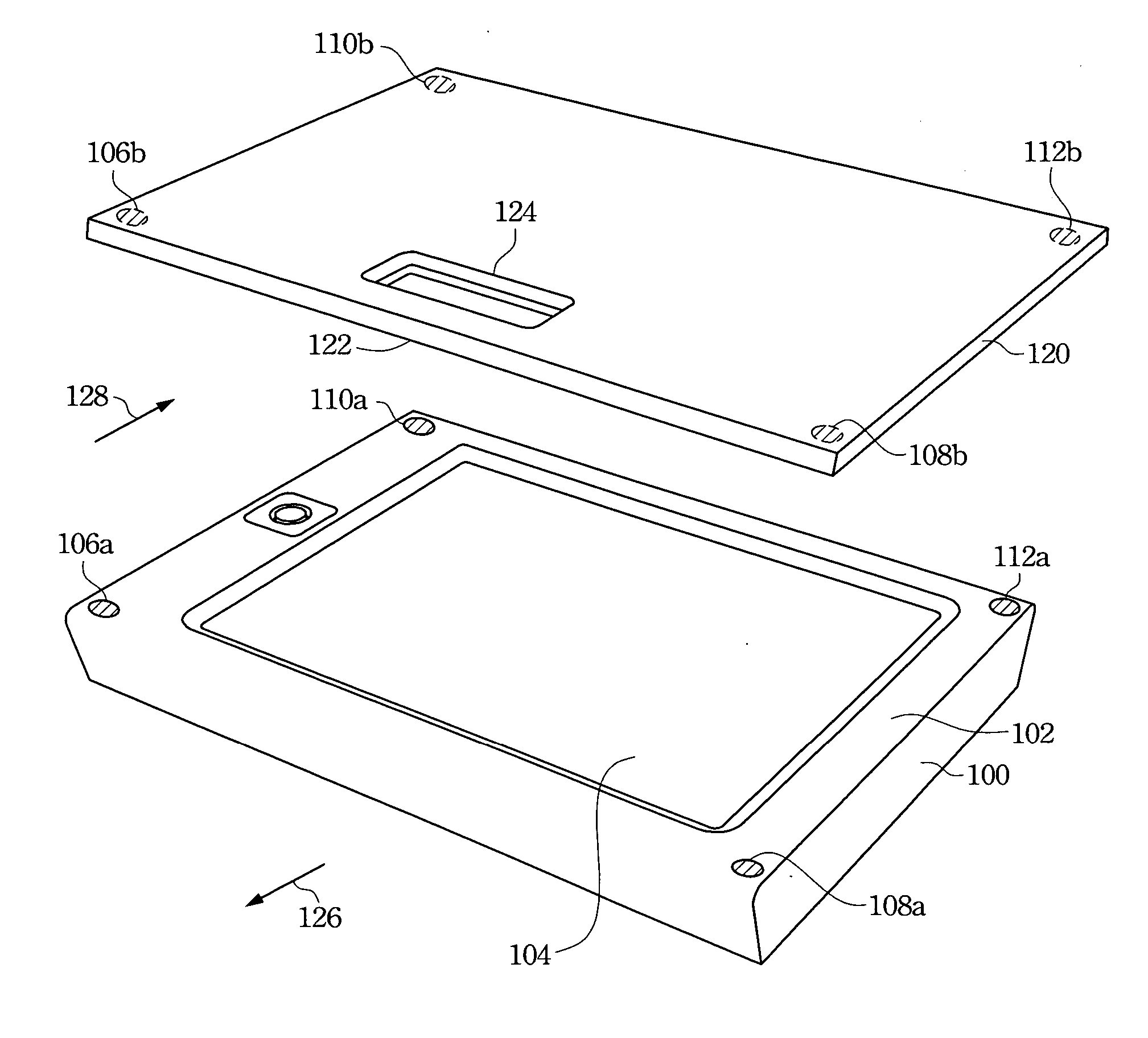
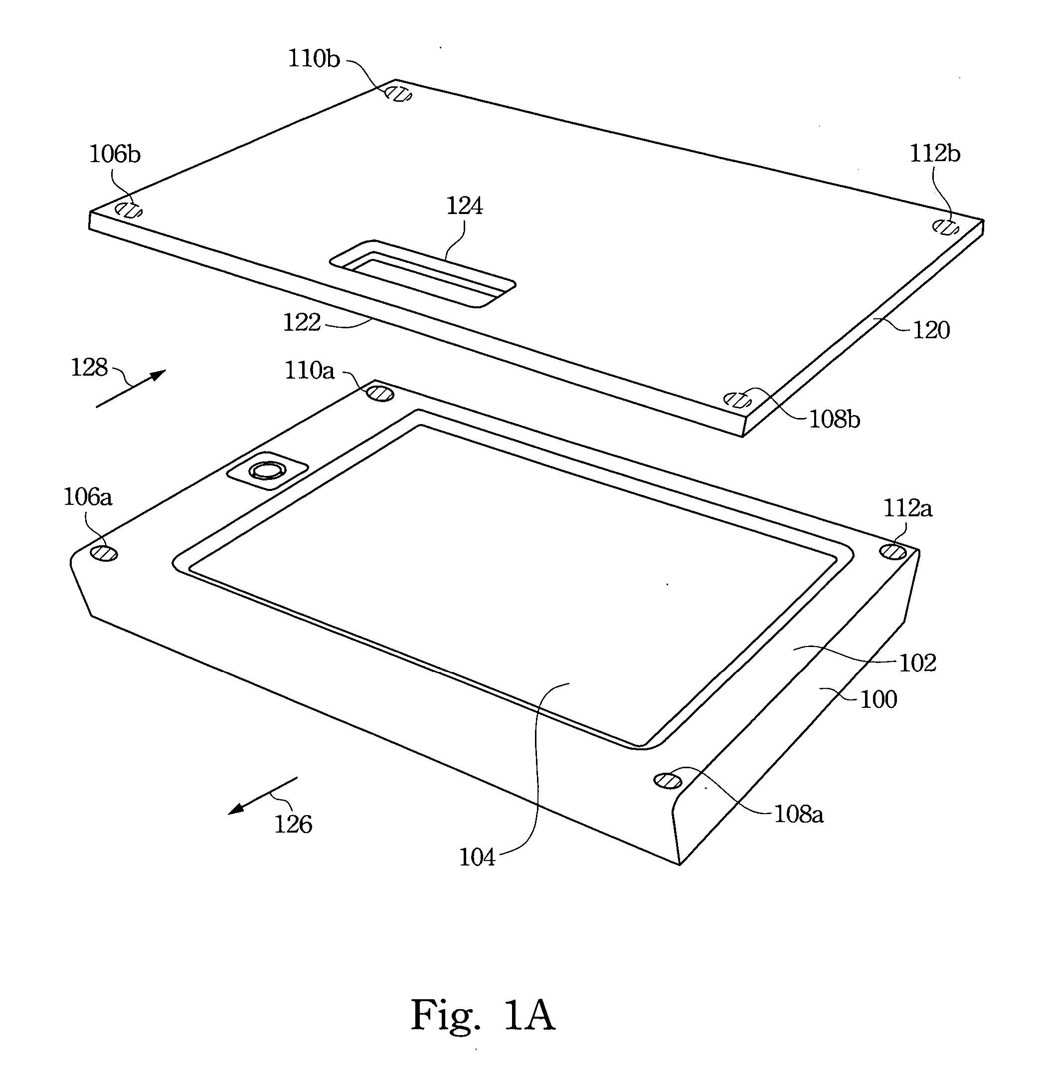
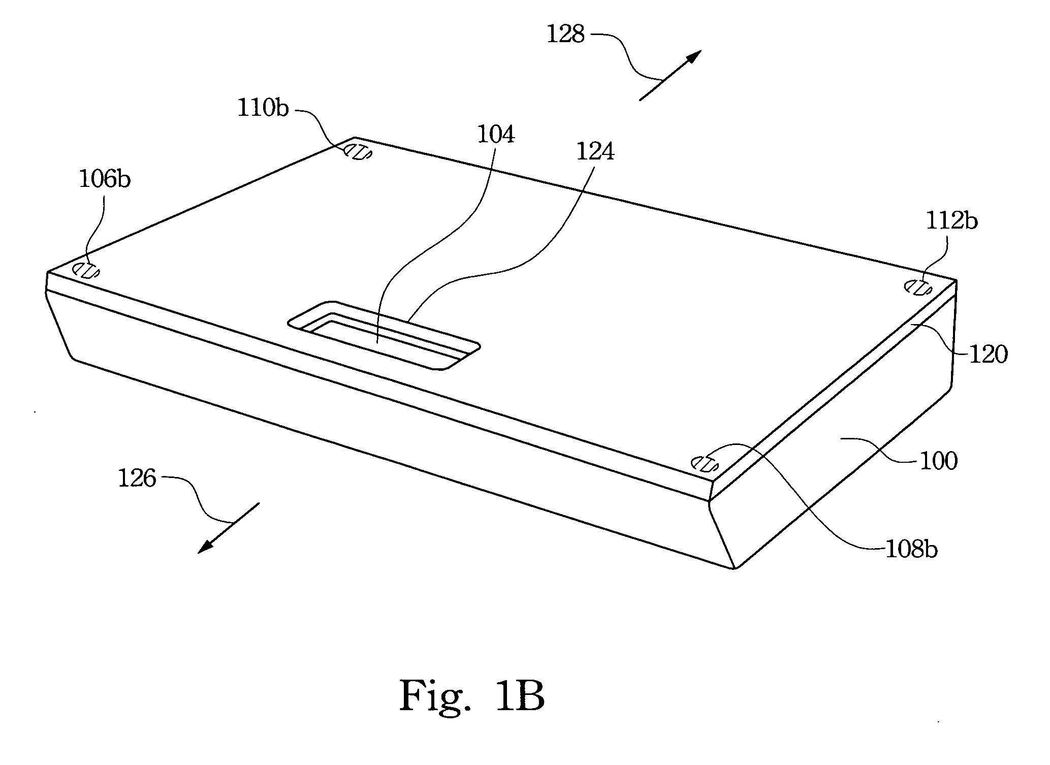
[0026]FIG. 1A illustrates an embodiment of the auto-aligning and connecting structure of the present invention. A portable electronic device 100 and its protective cover 120 are used to implement the embodiment.

[0027] It is observed in FIG. 1A that a display 104 is set on a first surface 102 of the electronic device 100. The portability of the electronic device 100 makes the display 104 more susceptible to damage. Hence a display protective cover 120 is needed to protect the display 104. The display protect...


PUM

PropertyMeasurementUnit
magneticaaaaaaaaaa
polarityaaaaaaaaaa
electromagneticaaaaaaaaaa

Abstract

An auto-aligning and connecting structure used to connect and align an electronic device and an accessory, wherein a plurality of first magnetic bodies are disposed on a first surface of the electrical device and a plurality of second magnetic bodies are disposed on a second surface of the accessory. The magnetic pole of the first magnetic bodies and the second magnetic bodies are appropriately arranged so the first magnetic bodies and the second magnetic bodies can attract each other when the first surface and the second surface approach each other. Then, the electronic device and the accessories are connected to each other when the first surface and the second surface connect.

Description

RELATED APPLICATIONS [0001] The present application is based on, and claims priority from, Taiwan Application Serial Number 94139006, filed Nov. 7, 2005, the disclosure of which is hereby incorporated by reference herein in its entirety. BACKGROUND [0002] 1. Field of Invention [0003] The present invention relates to an auto-aligning and connecting structure. More particularly, the present invention relates to an auto-aligning and connecting structure between an electronic device and an accessory. [0004] 2. Description of Related Art [0005] With the popularization of personal computers, electronic devices have continued to develop and flourish substantially in recent years. Conventional personal computers integrate many functions, such as video or audio signal playing, image data processing, and network communications, etc. However, conventional personal computers are often too heavy and bulky. As a result, many portable electronic devices have been created for more convenient and sp...

Claims


Application Information

Patent Timeline
Patent Type & Authority Applications(United States)
IPC IPC(8): H01F7/20
CPCG06F1/1632H01F7/0242
Inventor WANG, YI-SHENWANG, JOHN C.
Owner HTC CORP
Why Eureka
Try Eureka