System and apparatus for vehicle electrical power analysis

a technology for electrical power analysis and systems, applied in hardware monitoring, alarms, registering/indicating, etc., can solve problems such as system failure, unwarranted battery power failure, and unpredictability

Inactive Publication Date: 2007-05-10
VEPAC TECH PTE
View PDF4 Cites 50 Cited by
  • Summary
  • Abstract
  • Description
  • Claims
  • Application Information

AI Technical Summary

Benefits of technology

[0014] The present invention is particularly applicable to the monitoring of a terminal transient response voltage waveform and using that waveform to analyze the electrical power system of the vehicle under various working conditions. At the same time it can determine the cranking circuit quality, cranking torque capability, battery and starter cranking power capability, and alternator working status, to provide comprehensive information of the engine operational status.
[0015] It may be installed in a vehicle for on line measurement, a working station, or hand-held portable system, for industrial or professional application.

Problems solved by technology

However, due to the critical working environment of the battery such as, for example wide range of operating temperatures and high cranking currents, battery power failure is still unpredictable and may at times be without warning.
Any defective element in the power system will cause system failure.
However, these tests are not the actual load on the battery under operating conditions.
This means that such testing is under “off line” conditions that provide only static data.
Hence, these methods do not provide an accurate, dynamic measurement when there is interference by charging current, load current, ripple noise, and other noises, which exist in an actual operating environment.
A positive determination given by a CA or CCA test may not be correct if the battery is undersized for a particular application.
However, if the capacity of the battery is degraded, the SOC cannot used to determine the actual capacity of the battery.

Method used


Image

  • System and apparatus for vehicle electrical power analysis
  • System and apparatus for vehicle electrical power analysis
  • System and apparatus for vehicle electrical power analysis

Examples


Embodiment Construction

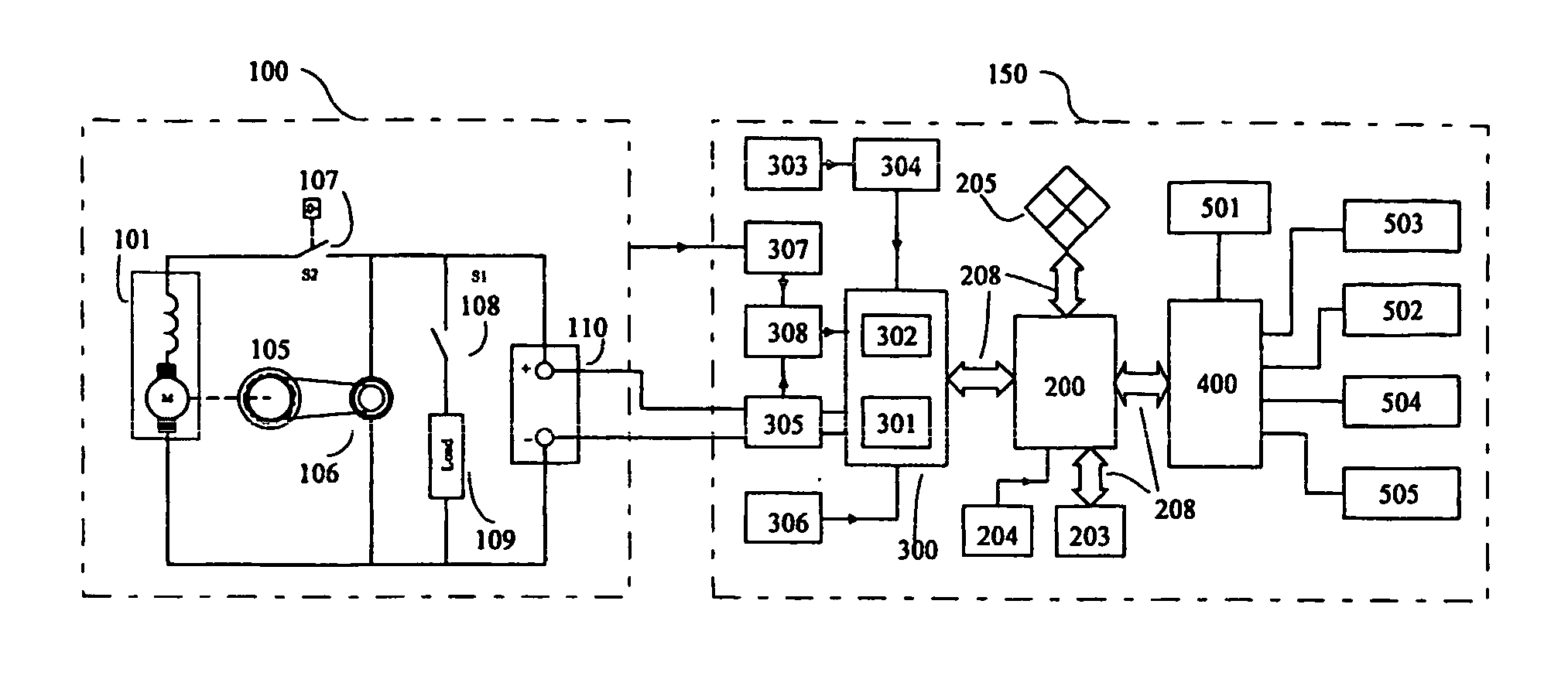
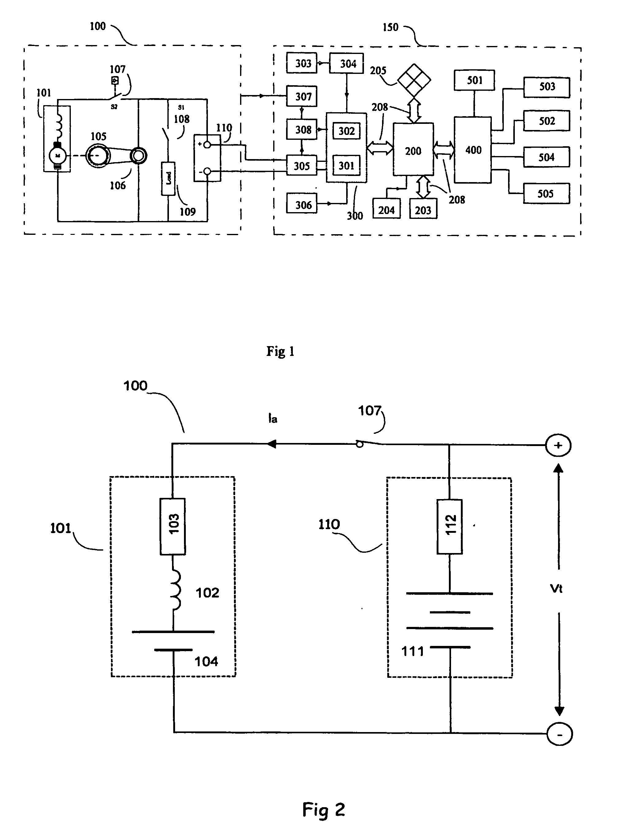
[0031] The embodiment illustrated in FIG. 1 shows an apparatus (150) for monitoring, testing, analyzing and the reporting of a vehicle's electrical power system. It is particularly applicable for measuring the terminal transient response voltage waveform and using that waveform to analyze the electrical power system of the vehicle at a number of different engine status conditions, including resting, cranking, and running. The apparatus (150) is able to evaluate the cranking circuit quality, cranking torque capability, battery-starter cranking power capability, and alternator charging condition. It can also provide a comprehensive report.

[0032] Referring first to FIG. 1, the vehicle electrical power system (100) consists of starter (101), internal combustion engine (105), generator or alternator (106), cranking switch (107), ignition switch (108), loads (109), and battery (110).

[0033] The internal combustion engine (105) is the main energy provider. It converts chemical energy to m...


PUM


Abstract

Apparatus for monitoring an electrical power supply system of a vehicle, the vehicle having a battery and internal combustion engine, an alternator, and a starter. The apparatus has a filter for determining the battery terminal voltage when the vehicle ignition is turned on. There is also a voltage gradient detector for detecting phase and gradient change of the battery terminal voltage when the vehicle ignition is on. A waveform detector is used for detecting and separating different waveforms when the vehicle ignition is on, and an engine-rotating sensor is used to sense a speed of the internal combustion engine when the vehicle ignition is on. Also included is a processor for processing at least one of the battery terminal voltage, the phase and gradient change, the different waveforms, and the speed of the internal combustion engine. An output is provided that is indicative of a condition of the electrical power supply system. A system for monitoring an electrical power supply system of a vehicle is also disclosed.

Description

FIELD OF THE INVENTION [0001] The present invention relates to a vehicle electrical power system and apparatus and refers particularly throughout exclusively to a system and apparatus for monitoring, analyzing, testing and reporting on the condition of a vehicle electrical power system. BACKGROUND TO THE INVENTION [0002] Modern automobiles have a high level of electronic equipment. As a result the reliability of electrical power supply of a vehicle is important. The inability to detect problems, and provide an early warning of problems, extracts from the reliability of the vehicle electrical power system. [0003] Many types of secondary storage batteries are used in the vehicle industry such as, for example, lead acid battery, nickel-cadmium battery, silver cadmium battery, and others. The most popularly used in the vehicle industry is the lead-acid battery. [0004] Chemical storage batteries, such as lead acid batteries used in automobiles, have existed for nearly a century with much...

Claims


Application Information

Patent Timeline
Patent Type & Authority Applications(United States)
IPC IPC(8): B60Q1/00G01M17/00G08B21/00G01R31/00G01R31/36
CPCG01R31/007G01R31/3693G01R31/3647
Inventor CHEW, SONG KITLEE, BON KWE
Owner VEPAC TECH PTE
Why Eureka
Try Eureka