Phase wavelength and polarization insensitive optical devices

a polarization insensitive, phase wavelength technology, applied in the direction of optical elements, optical radiation measurement, instruments, etc., can solve the problems of cumbersome devices that require external controllers, sensitive to polarization drift, cumbersome devices, etc., and achieve the effect of reducing the number of devices, and improving the accuracy of measurement results

Inactive Publication Date: 2007-05-10
SHAHAR ARIE
View PDF9 Cites 13 Cited by
  • Summary
  • Abstract
  • Description
  • Claims
  • Application Information

AI Technical Summary

Problems solved by technology

Devices that are based on a MZI structure have a disadvantage which is related to their basic principle of operation that is based on interference and phase shift.
In addition, when those devices are constructed from optical fibers, they are also sensitive to polarization drifts due to the birefringence of the fibers.
Accordingly, these devices need to be controlled by closed-loop phase and polarization controllers, making them cumbersome devices that require external controllers, are complicated, power consuming, and expensive.
However, when those devices are constructed from optical fibers, they are sensitive to polarization drifts due to the birefringence of the fibers.
Thus they suffer similar disadvantages as the MZI-based devices which are associated with the need to control polarization to compensate the polarization drifts.

Method used


Image

  • Phase wavelength and polarization insensitive optical devices
  • Phase wavelength and polarization insensitive optical devices
  • Phase wavelength and polarization insensitive optical devices

Examples


embodiment 600

[0130] An alternative design for a wavelength converter is illustrated by embodiment 600 of FIG. 6. As is explained below, device 600 may also be used as an optical threshold device. A CW beam 602 is injected at input port 610 of wavelength converter as signal 608, having intensity level 604 shown with reference to zero level 606. Signal 608 propagates through NLE 612 and emerges at radiation guide 614. Information port 678 may include optical amplifier 677 to boost the intensity of information signal 676 received at port 678. Information signal 676 is schematically illustrated as signal 670 having pulses 672 and 674. Signal 676 may pass through optional amplifier 677 and is directed by optical circulator 636, as control signal 618, into guide 614, towards NLE 612.

[0131] In the absence of control signal 618 corresponding to information signal 676, signal 608 may pass, as signal 616, through circulator 636 to appear as signal 621 propagating in light guide 638. Control signal 618 has...

embodiment 700

[0155] An alternative design for an optical chopper is illustrated by embodiment 700 of FIG. 7a. Input information signal 704, which may be a pulse 702, propagates at input port 706 and is amplified by optional optical amplifier 708 to emerge at light guide 710. Optional amplifier 708 is used to boost the intensity of signal 704 whenever needed to ensure that control signals 776 and 766, corresponding to input signal 704, will be able to drive NLEs 746 and 734 into saturation states. Signal 704 continuously propagates from guide 710 into splitting mechanism 714, which may include splitter 712. Splitter 712 may be a star splitter or a cascade of splitters or couplers.

[0156] Splitter 712 receives pulse 702 of information signal 704 from guide 710 and splits it into signals 733, 744, and 724, i.e., into pulses 732, 742, and 722 propagating in light guides 716, 720, and 721, respectively. These light guides are the output terminals of splitter 712. Terminals 716 and 720 of splitter 712 ...


PUM


Abstract

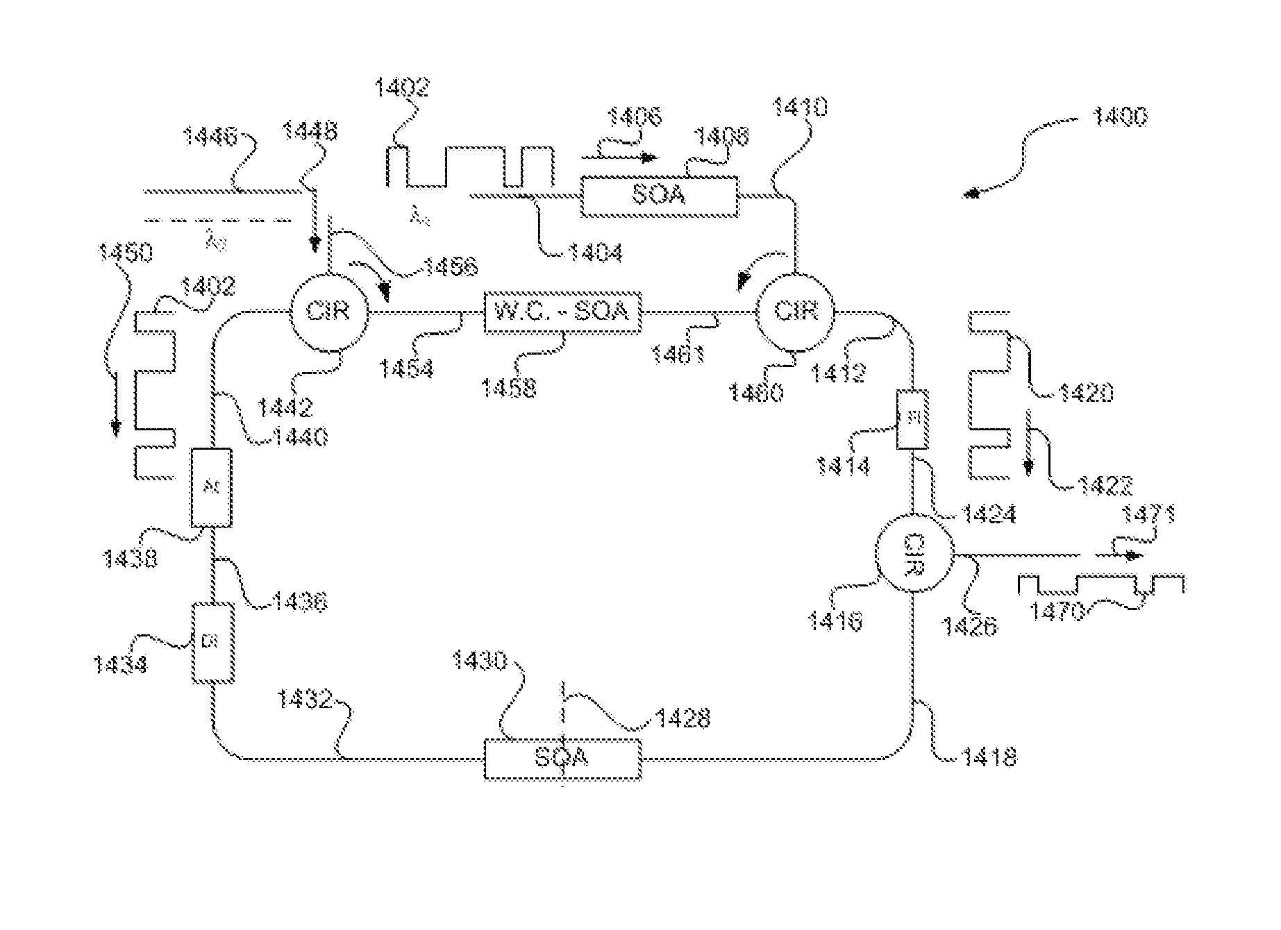
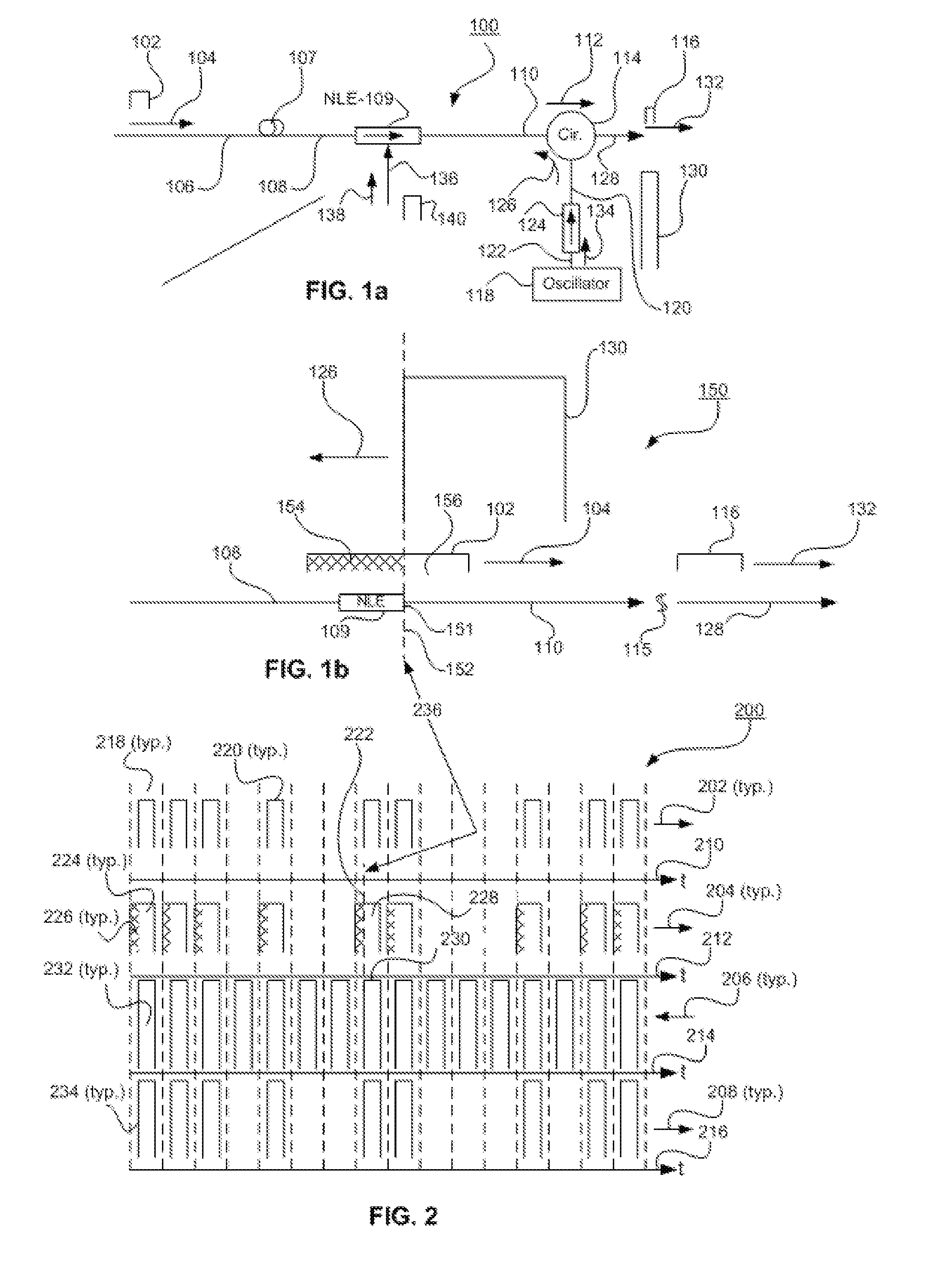
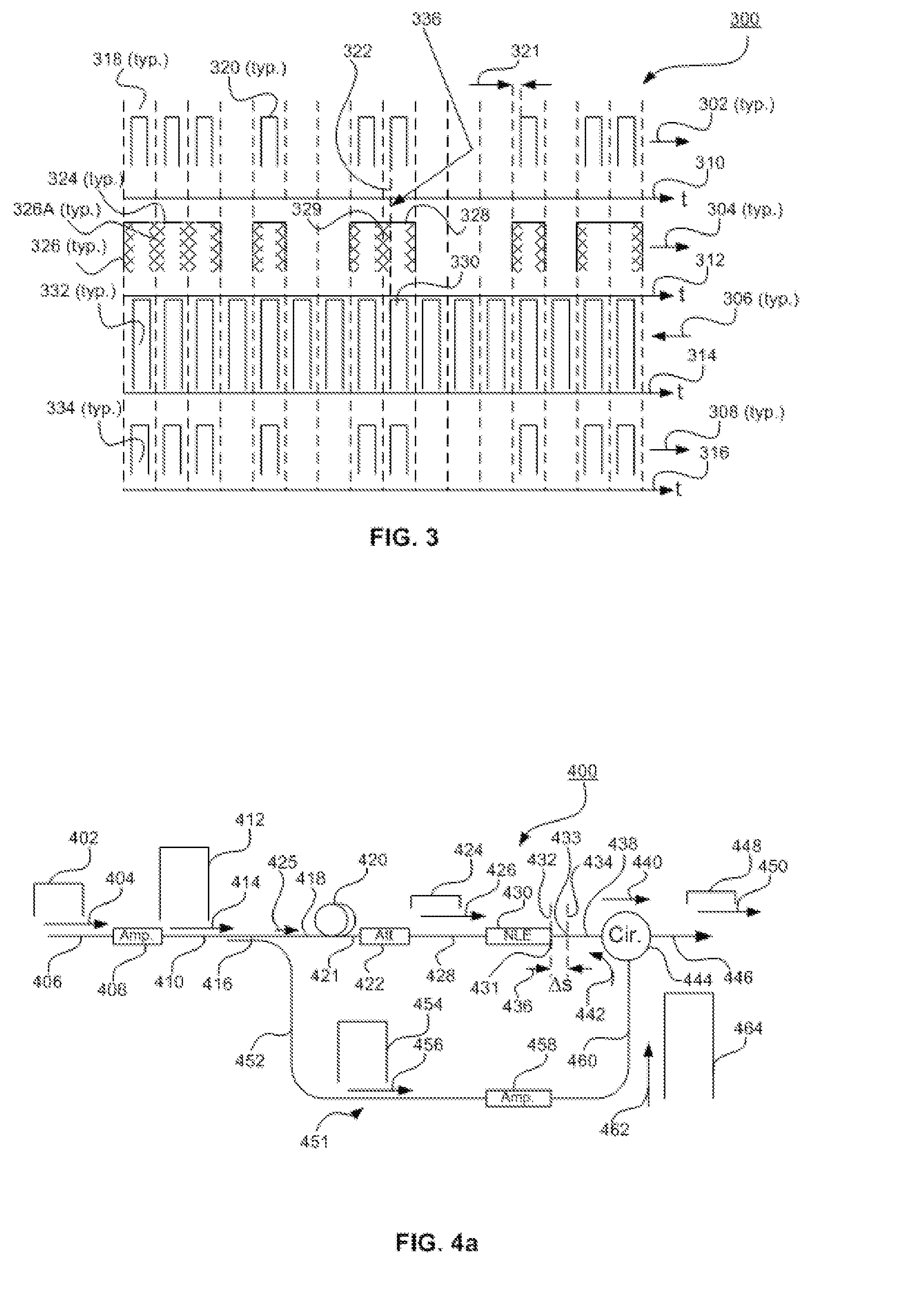
An optical chopper includes an optical loop having first and second terminals and includes first and second nonlinear elements. The optical loop is arranged to receive, at the first and the second terminals, a pulse-modulated signal and a continuous beam, respectively. The optical loop is arranged to cause the pulse-modulated signal and the continuous beam to counter-propagate in the loop and to produce in the first nonlinear element an inverted pulse-modulated signal having modulation which is inverted with respect to the pulse modulation of the pulse-modulated signal and to cause the inverted pulse-modulated signal to chop the pulse-modulated signal in the second nonlinear element.

Description

BACKGROUND—CROSS-REFERENCE TO RELATED APPLICATION [0001] This patent issued from an application that claims priority of my copending provisional patent application Ser. No. 60 / 734,143, filed Nov. 7, 2005BACKGROUND—FIELD [0002] Optical signal processing devices include optical communication devices and systems, optical computing devices and systems, including optical gating devices, optical chopping devices and systems, optical wavelength-conversion devices and systems, and optical bistable devices and systems for optical conversion of modulation formats. BACKGROUND—PRIOR ART [0003] The field of optical communication and computing has a strong demand for optical devices such as optical choppers, wavelength converters, and bistable devices. Such devices are used for transmitting and routing optical information for long distances and in metropolitan areas. Optical choppers may be used to correct optical dispersions along fibers that carry the optical information channels. The chopper r...

Claims


Application Information

Patent Timeline
Patent Type & Authority Applications(United States)
IPC IPC(8): G01J4/00
CPCG02F1/3515G02F1/3519G02F3/00G02F3/02G02F2201/16G02F2203/26G02F2203/70
Inventor SHAHAR, ARIE
Owner SHAHAR ARIE
Why Eureka
Try Eureka