Light detecting element and control method of light detecting element

a control method and light detecting technology, applied in the field of light detecting elements, can solve the problems of large output of signal light, inability to distinguish signal light from intermingled light, and limit the quantity of carriers generated according, so as to stimulate recombination mainly, the effect of increasing the probability of recombination

Inactive Publication Date: 2007-05-10
MATSUSHITA ELECTRIC WORKS LTD
View PDF6 Cites 37 Cited by
  • Summary
  • Abstract
  • Description
  • Claims
  • Application Information

AI Technical Summary

Benefits of technology

[0038] In this method, it is possible to gather the object carriers and the non-object carriers at the holding region in the light period and the extinction period respectively. It is also possible to stimulate the recombination mainly in the holding region by the transfer of the object carriers and the non-object carriers between the inside and the outside of the holding region. Moreover, probability of the recombination can be increased by repeating said transfer at plural times.

Problems solved by technology

Because there is a limitation in the quantity of the carriers generated according to the quantity of the received light.
Therefore, when the ambient light is received together with a signal light which includes object information in an application such as the above, there is a problem that large output cannot be obtained from the signal light since dynamic range of the element is reduced by the quantity of the ambient light.
Also, when the signal light is intermingled with the ambient light, there is a possibility that the signal light cannot be distinguished from the intermingled light if the ambient light fluctuates.
However, when the ambient light has a spectrum components spreading over a wide range such as sun light, influence of the ambient light cannot be sufficiently removed even through the optical filter.
However, in the prior art described Japanese Laid-open Patent Publication No. 2001-337166, there is a problem that the components of the signal light cannot be detected when the element is saturated.
That is, dynamic range for the signal light of the element becomes narrow under presence of the ambient light and therefore the prior art cannot still solve the problem that large output cannot be obtained from the light detecting element according to the signal light.
However, SN ratio cannot be sufficiently increased even though the irradiation quantity of the source is increased or the light receiving time of the element is lengthened.

Method used


Image

  • Light detecting element and control method of light detecting element
  • Light detecting element and control method of light detecting element
  • Light detecting element and control method of light detecting element

Examples


first embodiment

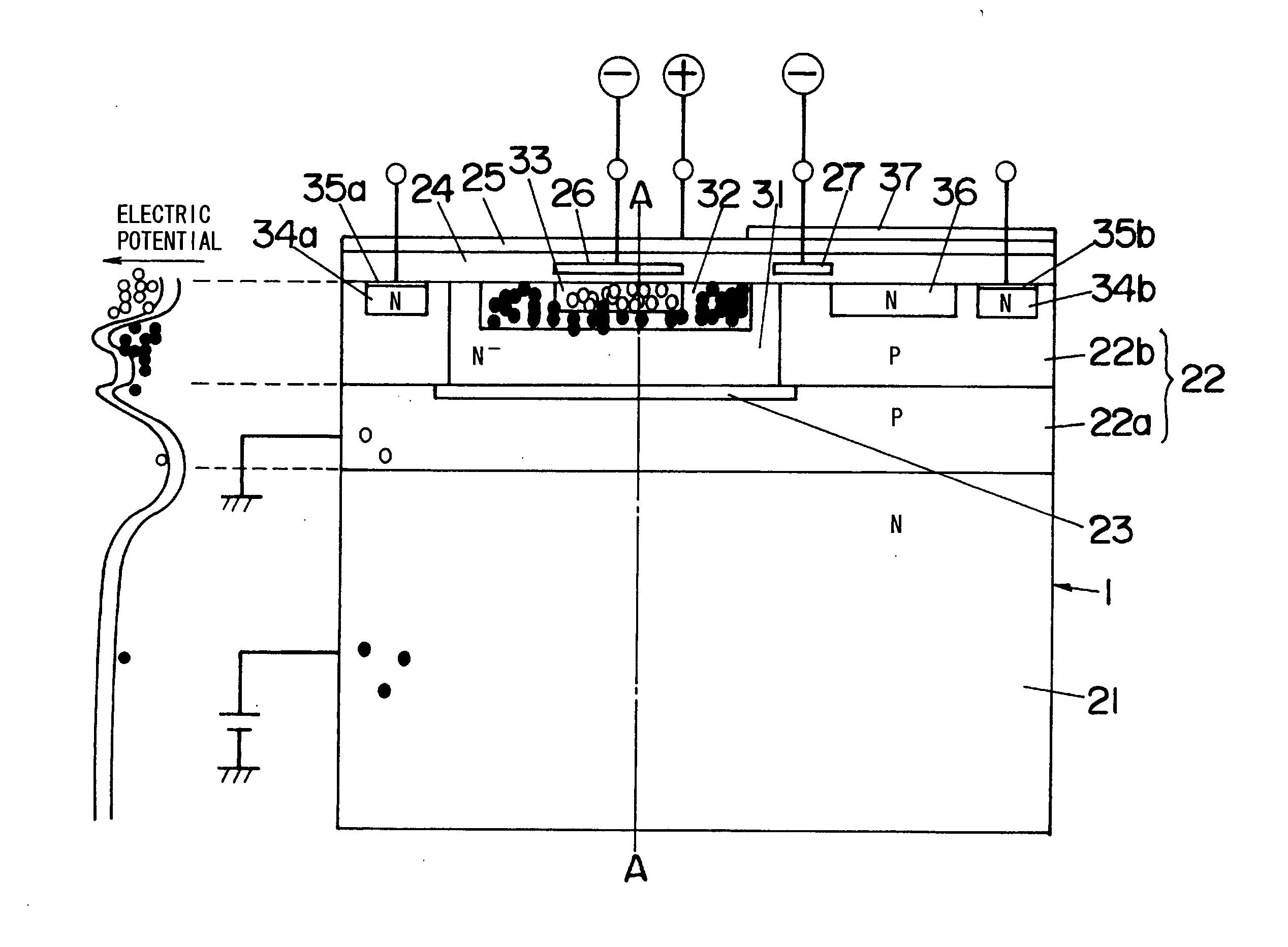
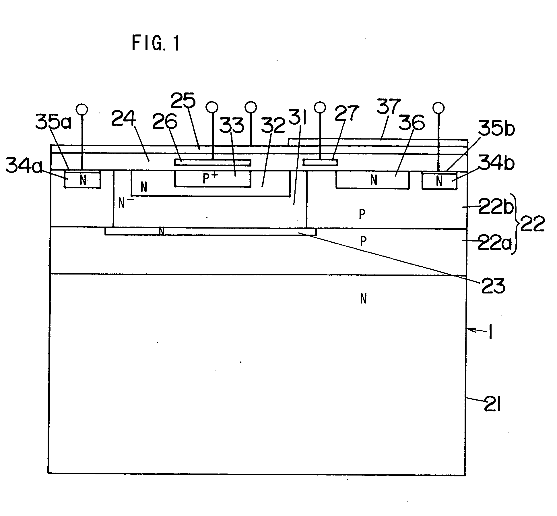
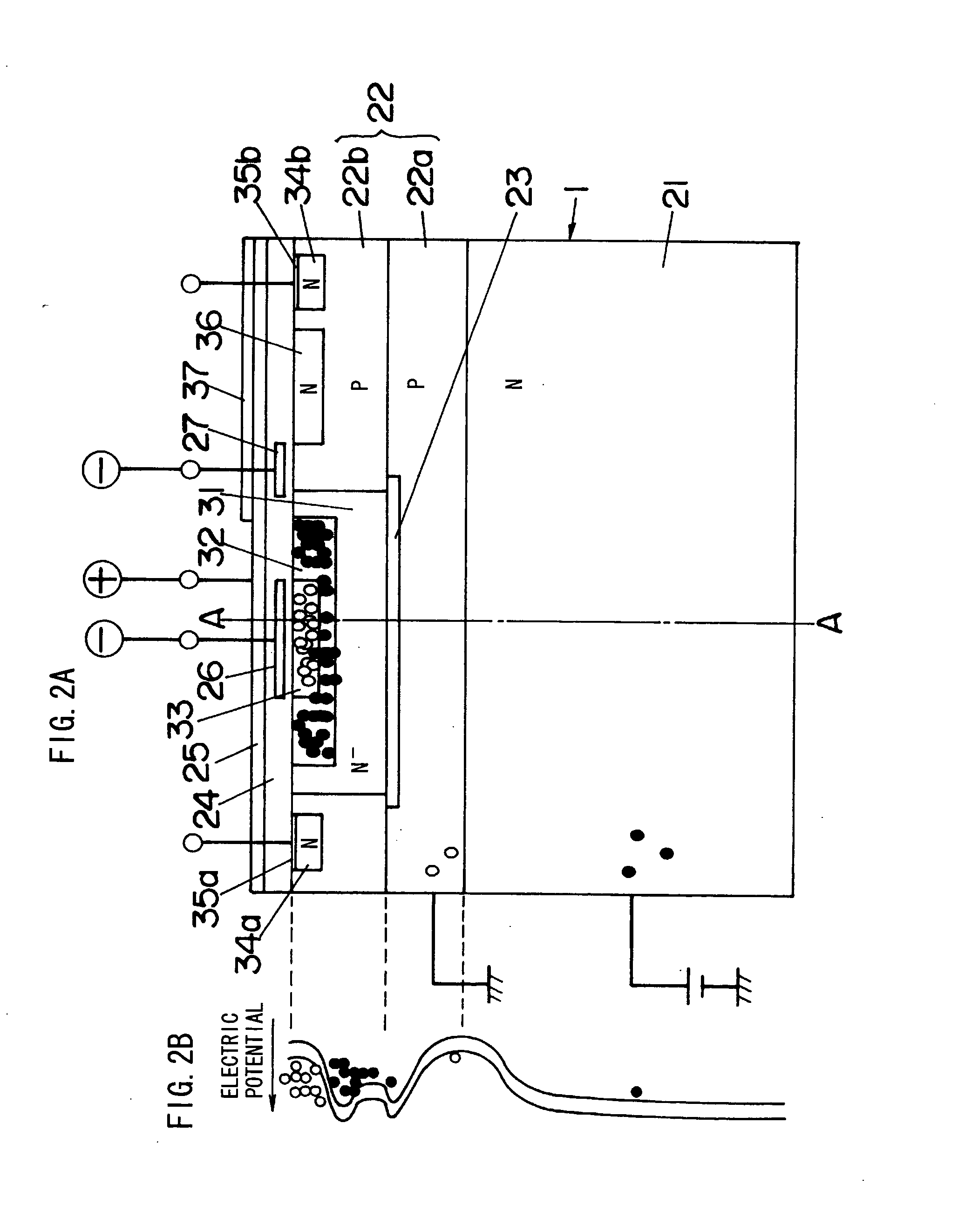
[0054]FIGS. 1-3 show a light detecting element 1 of a first embodiment according to the present invention, and FIG. 4 shows a distance sensor which measures distance by using the light detecting element 1. This sensor is constructed with a light source 2, the light detecting element 1 and a timing control unit 10. The source 2 emits light as output signal light on object space. This object space includes a physical object 3 (distance to be measured) away from the sensor. The element 1 receives light (hereinafter referred to as “input light”) from the object space. The input light includes the light (hereinafter referred to as “input signal light”) from the source 2 reflected by the object 3 depending on the situation. And the sensor obtains output corresponding to the received light from the element 1. The output represents quantity of the input light from the object space.

[0055] In a general way, the above-mentioned distance is measured by calculating light transmission time from a...

second embodiment

[0117] The element 1 of the second embodiment comprises a first photosensitive unit 11a which has suitable structure for picking out the holes and a second photosensitive unit 11b which has suitable structure for picking out the electrons. When the units 11a, 11b are structure of PN junction type or PIN type photodiode, it is possible to realize by reversing conductive type of the semiconductor. Also, in case of the MIS structure, it is possible to realize by reversing conductive type of the semiconductor and setting the electric potential applied to the gates to different polarities.

[0118] The holes generated at the unit 11a are held at the unit 13 through a gate unit 38a, while the electrons generated at the unit 11b are held at the unit 14 through a gate unit 38b. Timing for holding the holes at the unit 13 through the unit 38a is different from that for holding the electrons at the unit 14 through the unit 38b. The unit 10 of the second embodiment controls so as to selectively o...

third embodiment

[0129] In the third embodiment, the extinction period, the light period and the electric potential applied to the electrode 26 are appropriately adjusted, so that the number of the electrons held at the region 31 can be increased before the recombination as compared with the number of the holes held at the region 33. The electrons generated in the extinction period are not disposed of, but recombination can be stimulated between the electrons generated in the light period and the holes of which the number is equal or greater than that of the electrons generated in the extinction period, while the number of the electrons on the recombination can be greater than that of the holes. In short, it is possible eliminate the components of the ambient light while making the electrons remain after the recombination. FIG. 10 shows a state that the electrons and holes are respectively held at the regions 31 and 33 after the extinction period and the light period as described above.

[0130] In the...


PUM


Abstract

A light detecting element 1. The element 1 includes an element formation layer 22 which contains a well region 31. A surface electrode 25 is formed on the layer 22 through an insulating layer 24. The region 31 contains an electron holding region 32. The region 32 contains a hole holding region 33. The layer 24 contains a control electrode 26 facing the region 33 through the layer 24. Electrons and holes are generated at the layer 22. There are two selected states. In one state, by controlling each electric potential applied to the electrodes 25, 26, electrons are gathered at the region 32, while holes are held at the region 33. In another state, recombination is stimulated between the electrons and the holes. After the recombination, the remaining electrons are picked out as received light output.

Description

TECHNICAL FIELD [0001] The invention relates a light detecting element and a control method of the light detecting element. BACKGROUND ART [0002] A conventional light detecting element is known by different element such as a photodiode, phototransistor, CCD image sensor, etc. Such element is widely utilized in different application such as a photosensor which detects presence of a physical object based on variation of strength of the received light, optical (light) communication which uses light as transmission medium, distance sensor (rangefinder) which optically measures distance based on triangulation method, phase difference between the issued light and the received light, etc, image pick-up device such as a video camera or digital camera, or the like. [0003] In these applications, there is a case that a light source is used together with the light detecting element such as the photosensor which monitors intruder, the optical communication such as (infrared) light remote control...

Claims


Application Information

Patent Timeline
Patent Type & Authority Applications(United States)
IPC IPC(8): G02B5/32G01S7/4914G01S17/36H01L27/146H01L31/02H01L31/0352H01L31/103H01L31/113H04N5/335
CPCG01S17/36H01L27/14609G01S7/4914H04N5/335H01L31/103H04N25/00H01L27/148
Inventor HASHIMOTO, YUSUKETAKADA, YUJIKURIHARA, FUMIKAZUTSUNESADA, FUMI
Owner MATSUSHITA ELECTRIC WORKS LTD
Why Eureka
Try Eureka