Collimated optical system

a technology of collimated optical system and collimated lens, which is applied in the direction of telescopes, mountings, instruments, etc., can solve the problems of user's eyes needing to independently point in different directions, headaches, and user's eyes suffering headaches

Active Publication Date: 2007-05-10
ELBIT SYSTEMS OF AMERICA LLC
View PDF17 Cites 30 Cited by
  • Summary
  • Abstract
  • Description
  • Claims
  • Application Information

AI Technical Summary

Benefits of technology

[0005] Briefly, the present invention provides an optical system comprising a lens cell having a generally cylindrical lens cell body and an optical lens system therein. The lens cell body has a lens cell central longitudinal axis and a lens cell optical axis, eccentrically offset from the lens cell central longitudinal axis. A sleeve has a generally cylindrical sleeve body, an outer surface with a first longitudinal axis, and an inner surface with a second longitudinal axis, eccentrically offset from the first longitudinal axis. The lens cell is inserted into the sleeve. A housing has a generally cylindrical body into which the sleeve is at least partially inserted. The lens cell and the sleeve are rotated relative to each other and to the housing such that the lens cell optical axis is aligned in a desired location. After the lens cell optical axis is aligned in the desired location, the lens cell is fixedly connected to the sleeve and the sleeve is connected to the housing to prevent rotation of the sleeve relative to the housing.
[0007] Also, the present invention provides a method of manufacturing a collimated optical device comprising the steps of providing the elements of the optical system as described above; inserting the lens cell into the sleeve; inserting the sleeve at least partially into a housing, wherein the housing comprises a generally cylindrical housing body; independently rotating the sleeve and the lens cell relative to each other and to the housing until the optical device is at a desired collimation; securing the sleeve and the lens cell to each other to prevent rotation of the sleeve relative to the lens cell; and securing the sleeve to the housing to prevent rotation of the sleeve relative to the housing.

Problems solved by technology

Typical assembly procedures produce a device that is not collimated due to inconsistencies in the mounting of various optical elements within the device.
However, a binocular constructed from two uncollimated monoculars results in a user's eyes needing to independently point in different directions.
This is a very unnatural condition, and often causes the user to experience eyestrain and headaches.

Method used


Image

  • Collimated optical system
  • Collimated optical system
  • Collimated optical system

Examples


Embodiment Construction

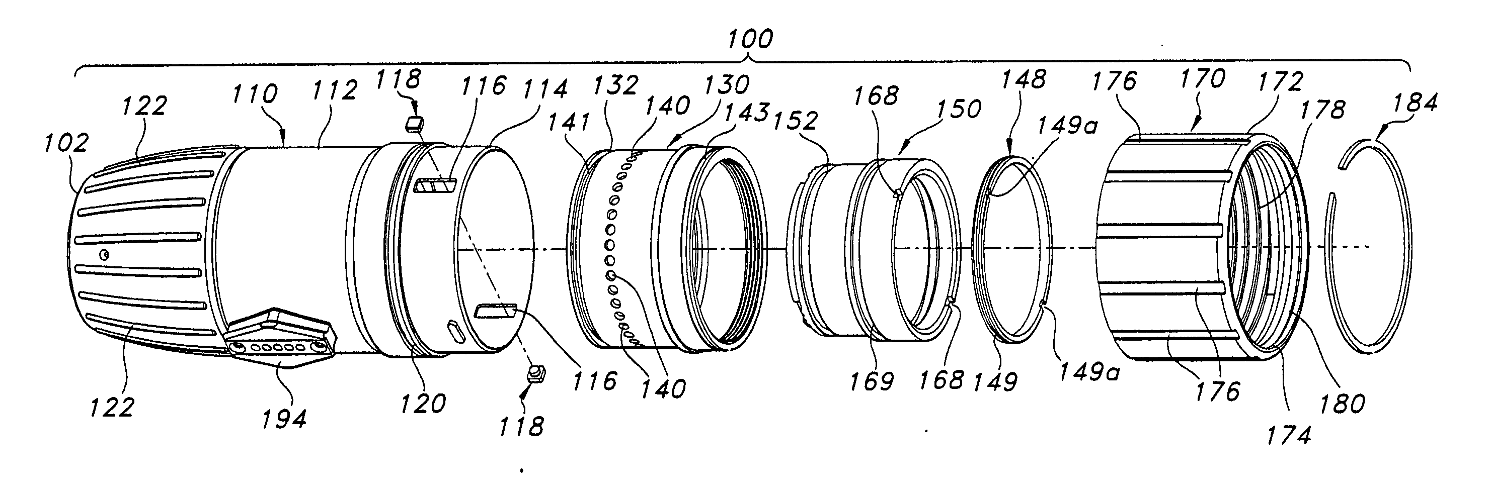
[0018] Certain terminology is used herein for convenience only and is not to be taken as a limitation on the present invention. The terminology includes the words specifically mentioned, derivatives thereof and words of similar import. As used herein, the term “input” is defined to mean a direction farther from a user when the monocular is in a use position as described herein and “output” is defined to mean a direction closer to the user when the monocular is in a use position as described herein. The following describes a preferred embodiment of the invention. However, it should be understood based on this disclosure, that the invention is not limited by the preferred embodiment of the invention.

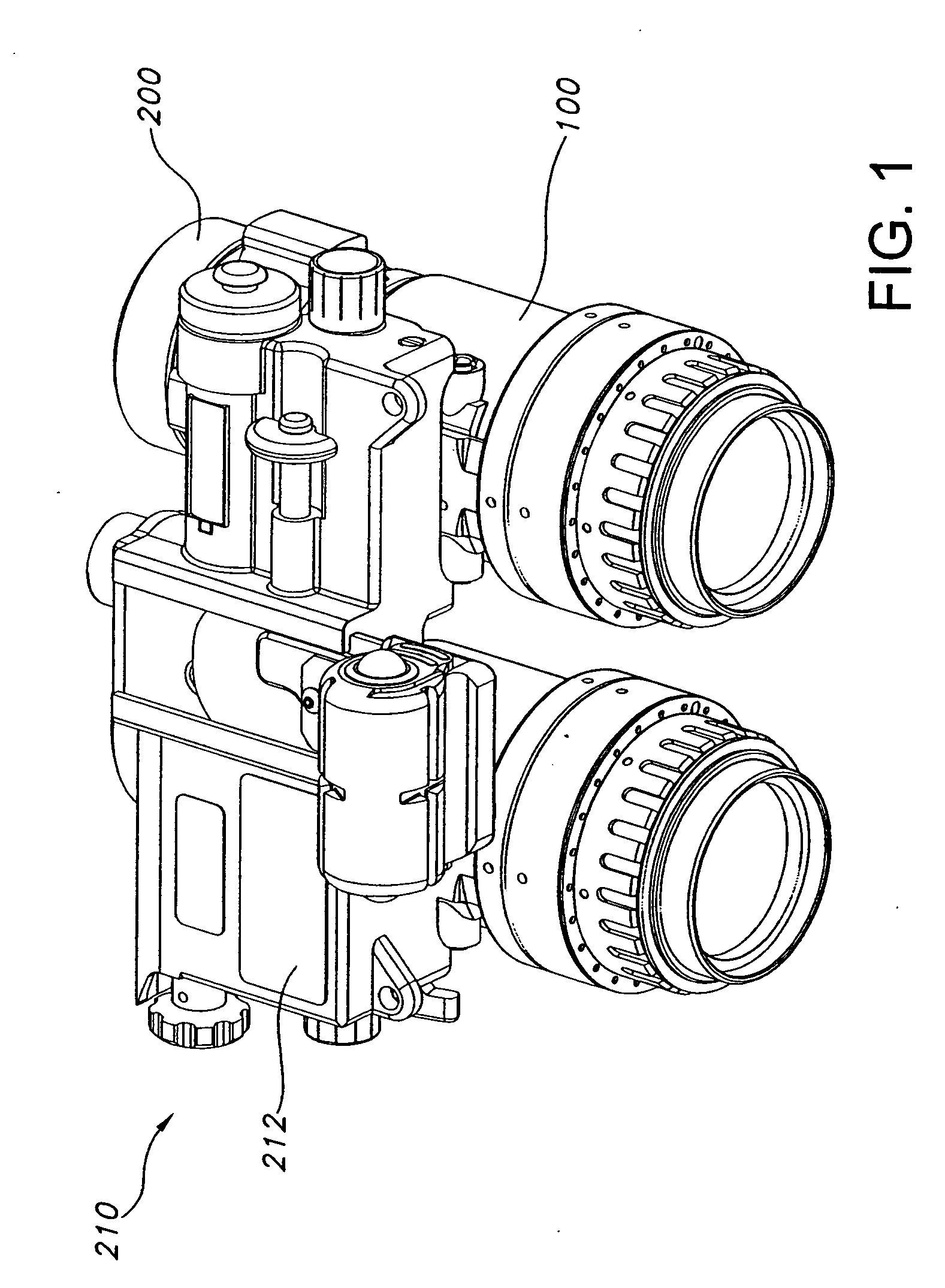
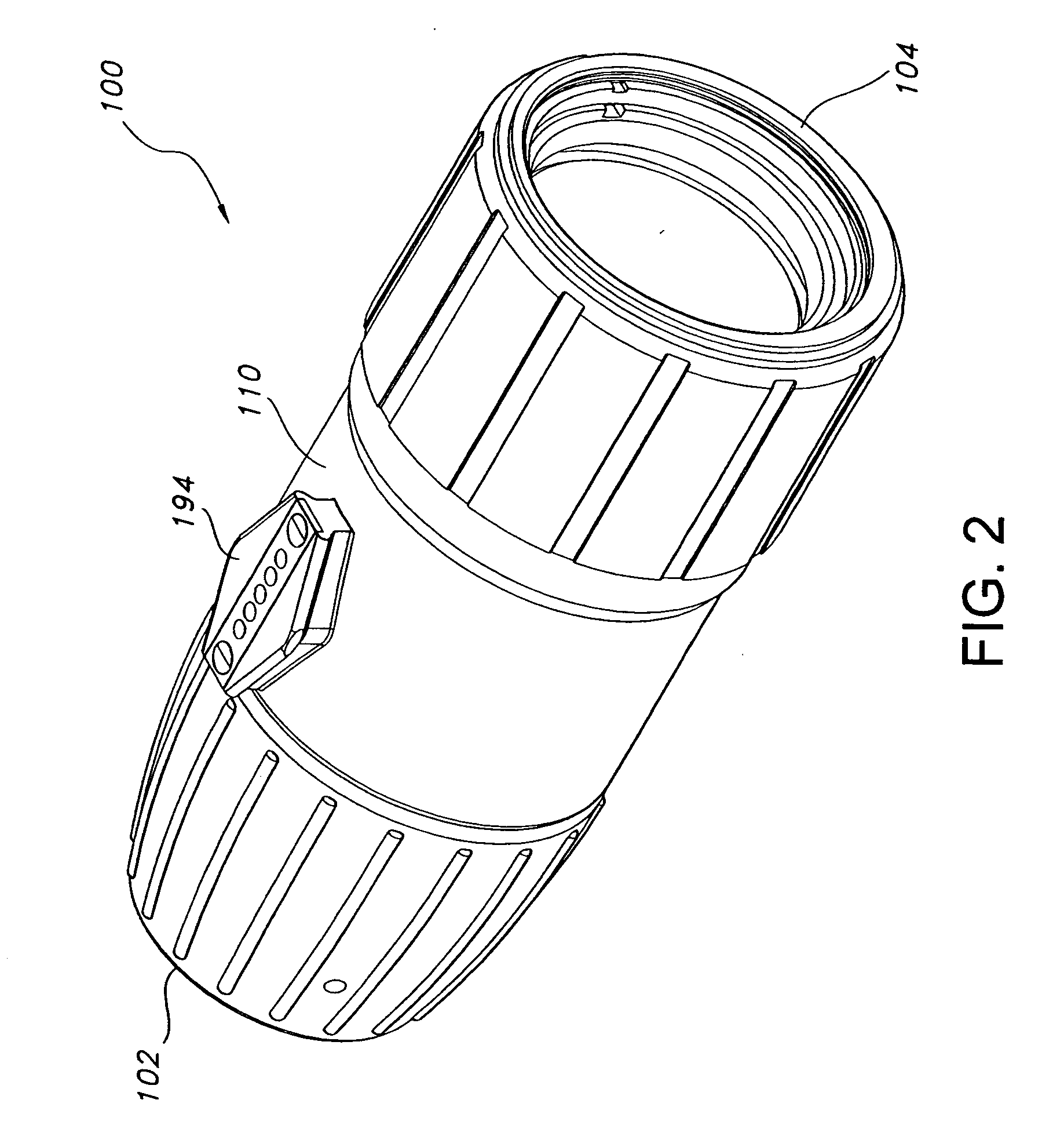
[0019] Referring to the drawings generally, a monocular 100 according to a preferred embodiment of the present invention is shown. The preferred monocular 100 can be used as a monocular or can be part of a night vision goggle (NVG) binocular 210, shown in FIG. 1. These devices are used to...


PUM


Abstract

An optical system provides a lens cell having a generally cylindrical lens cell body and an optical lens system therein. The lens cell body has a lens cell central longitudinal axis and a lens cell optical axis, eccentrically offset from the lens cell central longitudinal axis. A sleeve has a generally cylindrical sleeve body, an outer surface with a first longitudinal axis, and an inner surface with a second longitudinal axis, eccentrically offset from the first longitudinal axis. The lens cell is inserted into the sleeve. A housing has a generally cylindrical body into which the sleeve is at least partially inserted. The lens cell and the sleeve are rotated relative to each other and to the housing such that the lens cell optical axis is aligned in a desired location. After the lens cell optical axis is aligned in the desired location, the lens cell is fixedly connected to the sleeve and the sleeve is connected to the housing to prevent rotation of the sleeve relative to the housing.

Description

BACKGROUND OF THE INVENTION [0001] In a vision-assisting device, such as a monocular, the device is collimated when the output optical axis matches the input optical axis such that the beam of light entering the device is parallel with the beam of light exiting the device. Typical assembly procedures produce a device that is not collimated due to inconsistencies in the mounting of various optical elements within the device. A night vision device normally deviates from a collimated system due to the offset caused by the microchannel plate and twisted fiber optic within the device. [0002] When the device is not collimated, the image produced by the system is slightly out of alignment with the input image. Such slight misalignment is typically not a problem for a monocular. However, a binocular constructed from two uncollimated monoculars results in a user's eyes needing to independently point in different directions. This is a very unnatural condition, and often causes the user to exp...

Claims


Application Information

Patent Timeline
Patent Type & Authority Applications(United States)
IPC IPC(8): G02B7/02
CPCG02B23/12G02B23/18G02B27/62
Inventor FLOYD, MICHAEL R.BRILLHART, STEVEN A.
Owner ELBIT SYSTEMS OF AMERICA LLC
Why Eureka
Try Eureka