Power supply for a cochlear implant

a cochlear implant and power supply technology, applied in the field of cochlear implants, can solve the problems of high energy density, restrictions on the type and dimension of power supply that can be used, and people are therefore unable to derive suitable benefits from conventional hearing aid systems, so as to achieve the effect of maximising the performance of devices

Inactive Publication Date: 2007-05-10
COCHLEAR LIMITED
View PDF29 Cites 20 Cited by
  • Summary
  • Abstract
  • Description
  • Claims
  • Application Information

AI Technical Summary

Benefits of technology

[0021] In a preferred embodiment, the third battery is connected in parallel by the switching means with whichever of the first and second batteries is exhibiting worse performance, which could be determined by which battery has the lower voltage. In this embodiment, the batteries will tend to work at substantially the same voltage and thus substantially evenly share the power load of the electrically powered device. Such an arrangement has the advantage that the probability of failure of a power supply having three batteries in such an arrangement reduces to 2% and so the probability of a successful battery change increases to 98%, based on batteries having an 8% probability of being faulty.
[0034] In these aspects, the batteries will tend to work at substantially the same voltage and thus share the power load of the prosthesis. Such an arrangement has the advantage that the probability of failure of a power supply having three batteries reduces to 2% and so the probability of a successful battery change increases to 98%. Such an arrangement also ensures that should the system power requirements be too great for the two batteries in series alone, the third battery will be electrically connected to cover any increased power requirements.
[0035] The switching means of the present invention preferably comprises an analog changeover switch. In preferred embodiments of the seventh aspect of the present invention, a low power comparator may be used to make the determination of satisfactory operation of the first and second batteries, for example by being used to compare the mid-point from a voltage divider positioned across the first and second batteries. Such a comparator may also be used in voltage measurements of the batteries in accordance with the first to sixth aspects of the present invention. In such embodiments, when the mid-point of the batteries indicates a mismatch, the comparator preferably operates the switch to connect the third battery in parallel with whichever of the first or second batteries has the lowest voltage. As the third battery will approximately halve the demand on the battery with which it is connected in parallel, the other of the first and second batteries will be drained at a faster rate. Hence, it is expected that it will repeatedly be necessary to connect the third battery across the other of the first and second batteries. The control system preferably causes such switching of the third battery between the first and second batteries to occur based on the voltages measured by the voltage divider. In this regard, a small amount of hysteresis (eg. about 4 mV) is preferably provided to avoid excessive switching. The switching rate is preferably limited to below about 50 kHz. Such regular switching of the third battery between the first and second batteries will assist in ensuring the first and second batteries are drained at a similar rate.
[0050] Such a step ensures that the measurement of performance of the first battery and the second battery, such as by measuring the voltage across each of the first and second batteries, is carried out without the performance of the third battery affecting the measurement.
[0051] Preferred embodiments of the present invention provide a system designed to maximise the performance of devices such as cochlear implants and other devices that are reliant upon installed battery power, in the presence of an unreliable power supply. Preferred embodiments of the invention may also provide a system designed to cater for the power requirements of a wide range of cochlear implant or tissue-stimulating implant users with varying system requirements.

Problems solved by technology

These people are thus unable to derive suitable benefit from conventional hearing aid systems, no matter how loud the acoustic stimulus is made, because there is damage to, or an absence of the mechanism for nerve impulses to be generated from sound in the normal manner.
However, with the introduction and increased usage of BTE devices and the desire to provide such devices that are small enough to fit behind the ear of the user or to be discretely worn on the head of the user, the space requirements of the device lead to restrictions in the type and dimension of power supply that can be utilised.
Where previously the number of cells required to form the power supply of the device has been relatively unrestricted, such more discrete and compact BTE devices have limited space to house the cells to be used to supply the power for the implant.
They have a very high energy density and can supply a device's requirements for a relatively long period of time relative to their size and weight.
As supplied, these cells do, however, occasionally suffer from a relatively high failure rate.
Given that some cochlear implants rely on two satisfactory cells being used in series, the chance that a user will have a problem after replacing a pair of such battery cells increases to 15%.
Such problems include finding that the cochlear implant still does not work or stops working satisfactorily after a relatively short time following the insertion of new cells.
These problems can then result in the user incorrectly believing that their device has failed and sending the device for repair or replacement, or finding themselves unexpectedly losing their ability to experience hearing sensation after they were sure that the power supply would last for a specific period of time.

Method used


Image

  • Power supply for a cochlear implant
  • Power supply for a cochlear implant
  • Power supply for a cochlear implant

Examples


Embodiment Construction

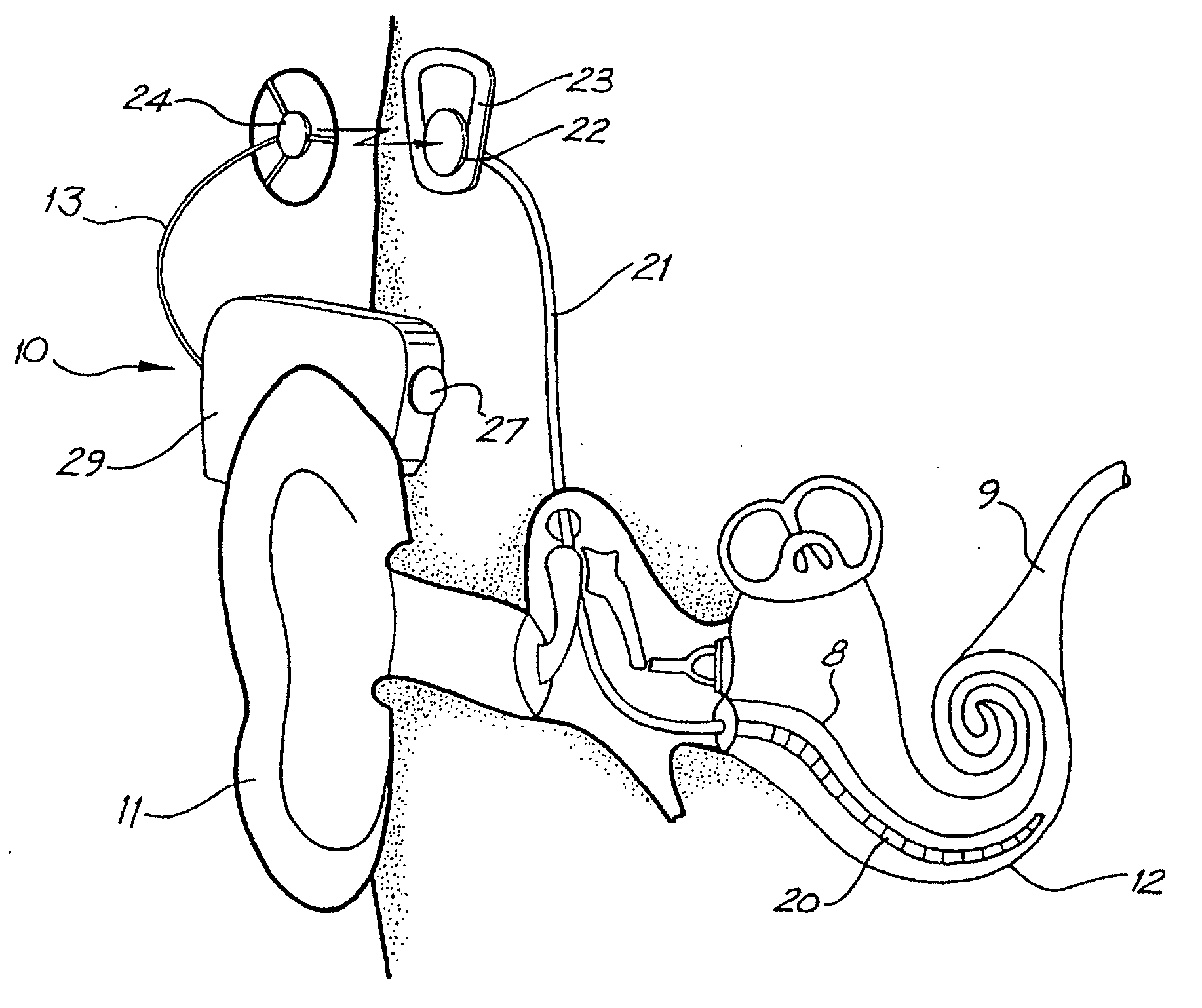
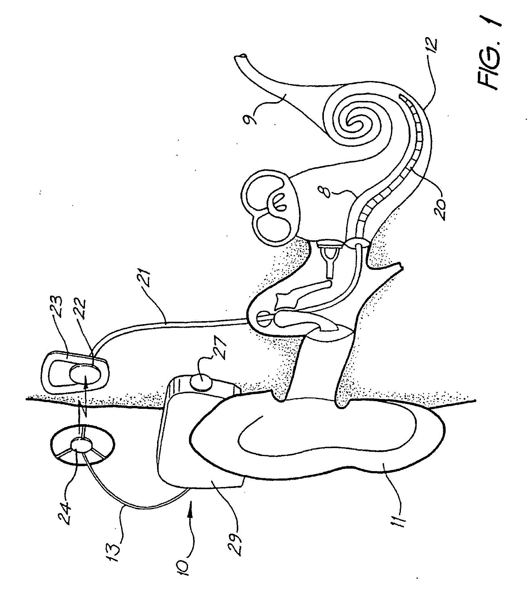
[0061] An example of a device powered by the power supply system of the present invention can be seen in FIG. 1.

[0062] One embodiment of a cochlear implant utilising the present invention is depicted in FIG. 1 and consists of two main components, namely an external component 10 including a speech processor 29, and an internal component including an implanted receiver and stimulator unit 22.

[0063] The external component 10 includes an on-board microphone 27. The case of the external component 10 is constructed and arranged so that it can sit on the outer ear 11 of the implantee. The case of the external component is also constructed so that it contains a power supply in accordance with the present invention. The power supply provides the power for the entire implant system.

[0064] A cable 13 extends from the case of the external component 10 to an external transmitter coil 24 which transmits electrical signals to the implanted unit 22 via a radio frequency (RF) Link.

[0065] The imp...


PUM


Abstract

A power supply control system for use with a tissue stimulating prosthesis, such as a cochlear implant. The power supply control system comprises a first battery, a second battery, at least a third battery, and a switching system. The first and second batteries are electrically connected in series to provide power to the prosthesis, while the third battery is electrically connectable through the switching means in parallel with either the first battery. The third battery is electrically connected by the control system in parallel with whichever one of said first battery or said second battery has lowest voltage.

Description

FIELD OF THE INVENTION [0001] The present invention relates to a power supply for an implant, such as a cochlear implant, and in particular, to a power supply having a plurality of batteries and a means for controlling the use of the batteries by the implant. BACKGROUND ART [0002] In many people who are profoundly deaf, the reason for deafness is absence of, or destruction of, the hair cells in the cochlea which transduce acoustic signals into nerve impulses. These people are thus unable to derive suitable benefit from conventional hearing aid systems, no matter how loud the acoustic stimulus is made, because there is damage to, or an absence of the mechanism for nerve impulses to be generated from sound in the normal manner. [0003] It is for this purpose that cochlear implant systems have been developed. Such systems bypass the hair cells in the cochlea and directly deliver electrical stimulation to the auditory nerve fibres, thereby allowing the brain to perceive a hearing sensati...

Claims


Application Information

Patent Timeline
Patent Type & Authority Applications(United States)
IPC IPC(8): H04R25/00A61F11/00A61F2/18A61F11/04A61N1/36A61N1/378H02J7/00
CPCA61N1/36032A61N1/378H02J7/0024H02J7/0063H04R25/606A61N1/36038H02J7/007182H02J2310/23
Inventor SELIGMAN, PETER MISHA
Owner COCHLEAR LIMITED
Why Eureka
Try Eureka