Bearing apparatus for supporting pinion shaft

a technology for bearings and shafts, applied in the direction of bearing units, rigid support, gearing details, etc., can solve problems such as affecting the fuel consumption of vehicles, and achieve the effect of increasing the load carrying capacity

Inactive Publication Date: 2007-05-10
JTEKT CORP
View PDF12 Cites 13 Cited by
  • Summary
  • Abstract
  • Description
  • Claims
  • Application Information

AI Technical Summary

Benefits of technology

[0011] Moreover, the contact angle θ between the ball and the inner and outer ring raceways in the rolling bearing on the companion flange side satisfies, for example 30°≦θ≦45°. Generally, in an angular contact ball bearing for high speed revolution, since a contact angle θ′ between a ball and inner and outer ring raceways is 20°≦θ′≦25°, the contact angle θ of the present invention bec

Problems solved by technology

When the tapered roller bearing with large load carrying capacity is used, frictional resistance will increases, so

Method used


Image

  • Bearing apparatus for supporting pinion shaft
  • Bearing apparatus for supporting pinion shaft
  • Bearing apparatus for supporting pinion shaft

Examples


second embodiment

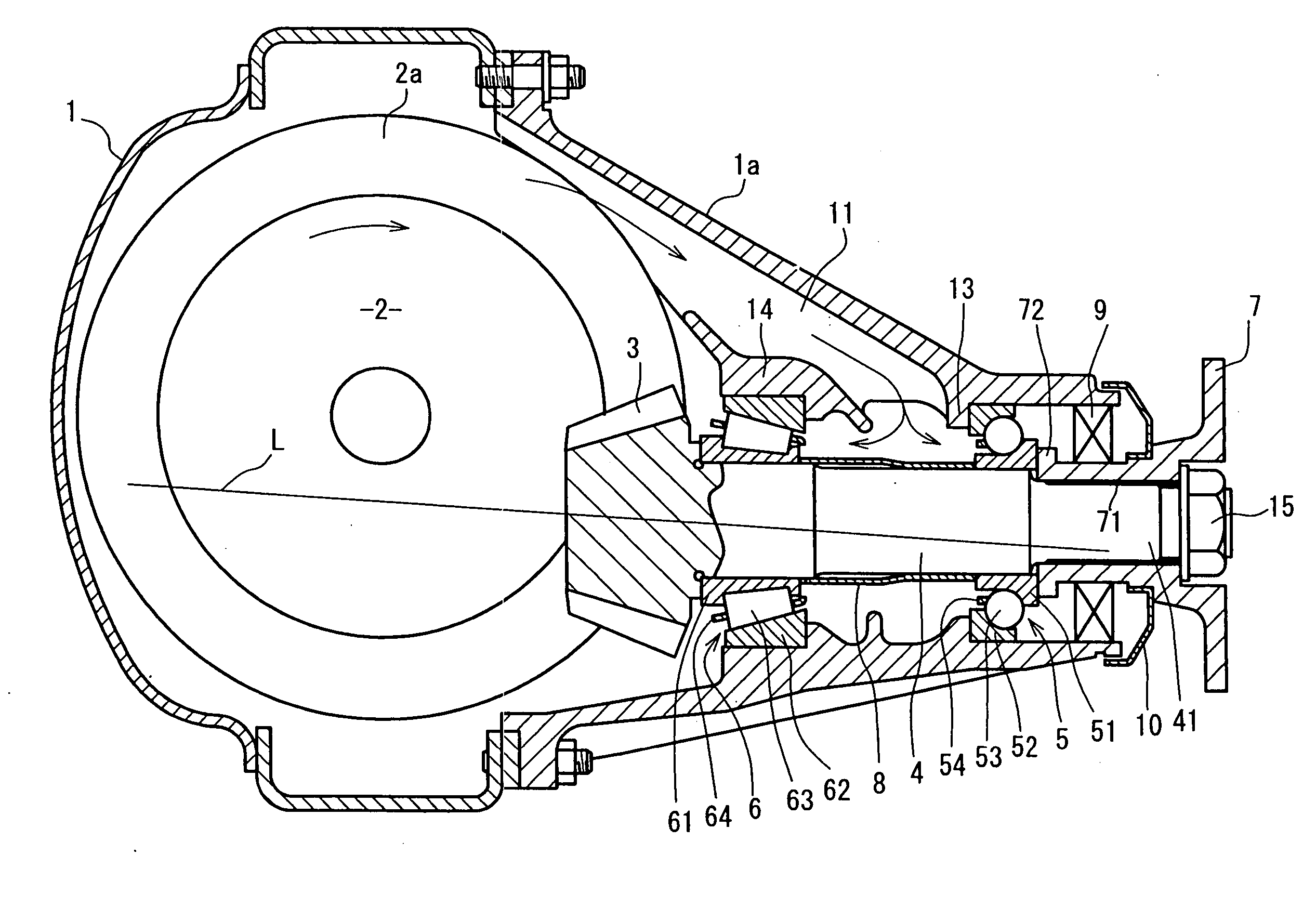
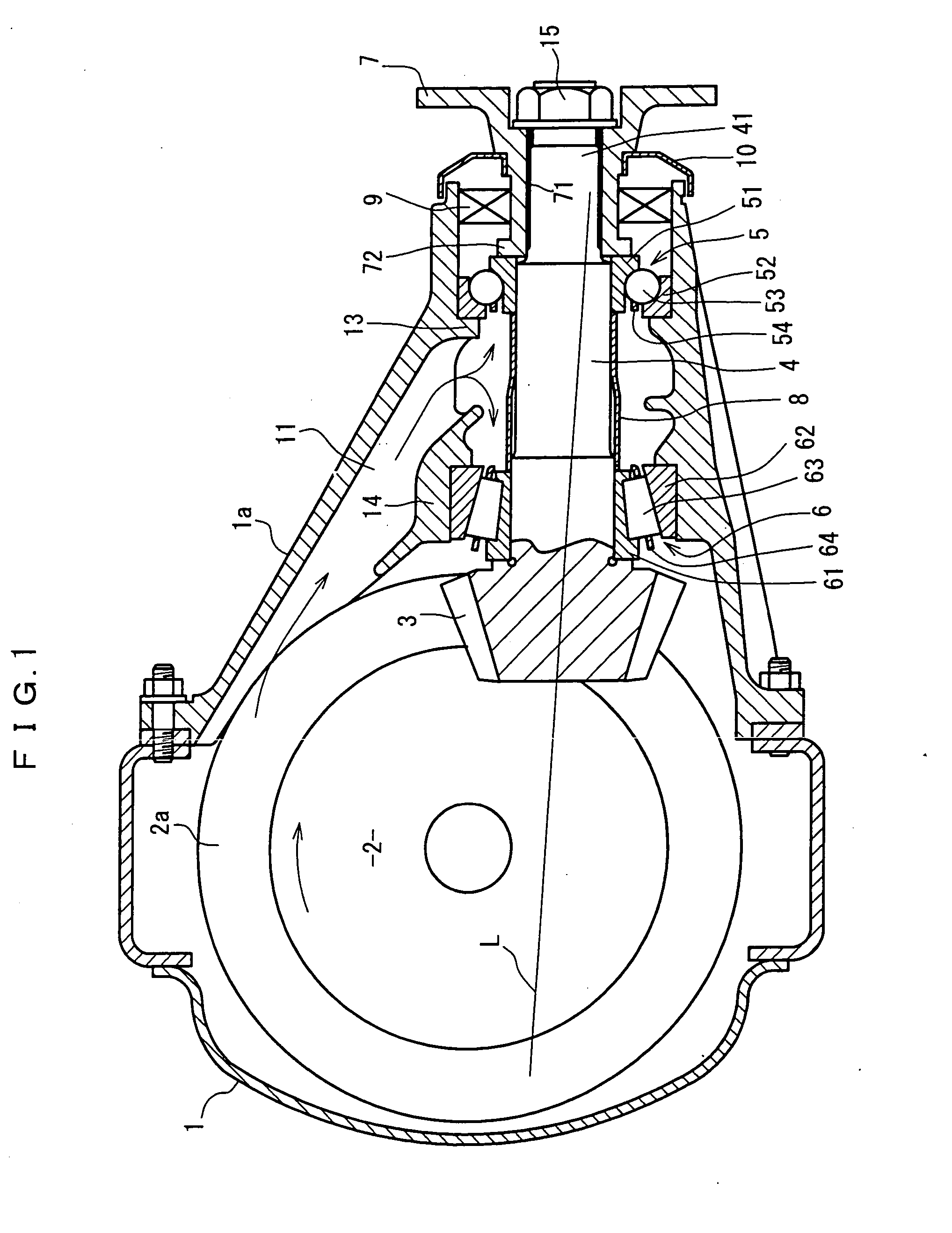
[0049] Description will be made of the present invention using FIG. 5 through FIG. 7.

[0050]FIG. 5 is a cross-sectional view of a differential mechanism to which a bearing apparatus for supporting a pinion shaft in the second embodiment is applied, FIG. 6 is a partially expanded cross-sectional view of the bearing apparatus for supporting the pinion shaft shown in FIG. 5, and FIG. 7 is an expanded sectional view of a seal portion of the bearing apparatus for supporting the pinion shaft shown in FIG. 5.

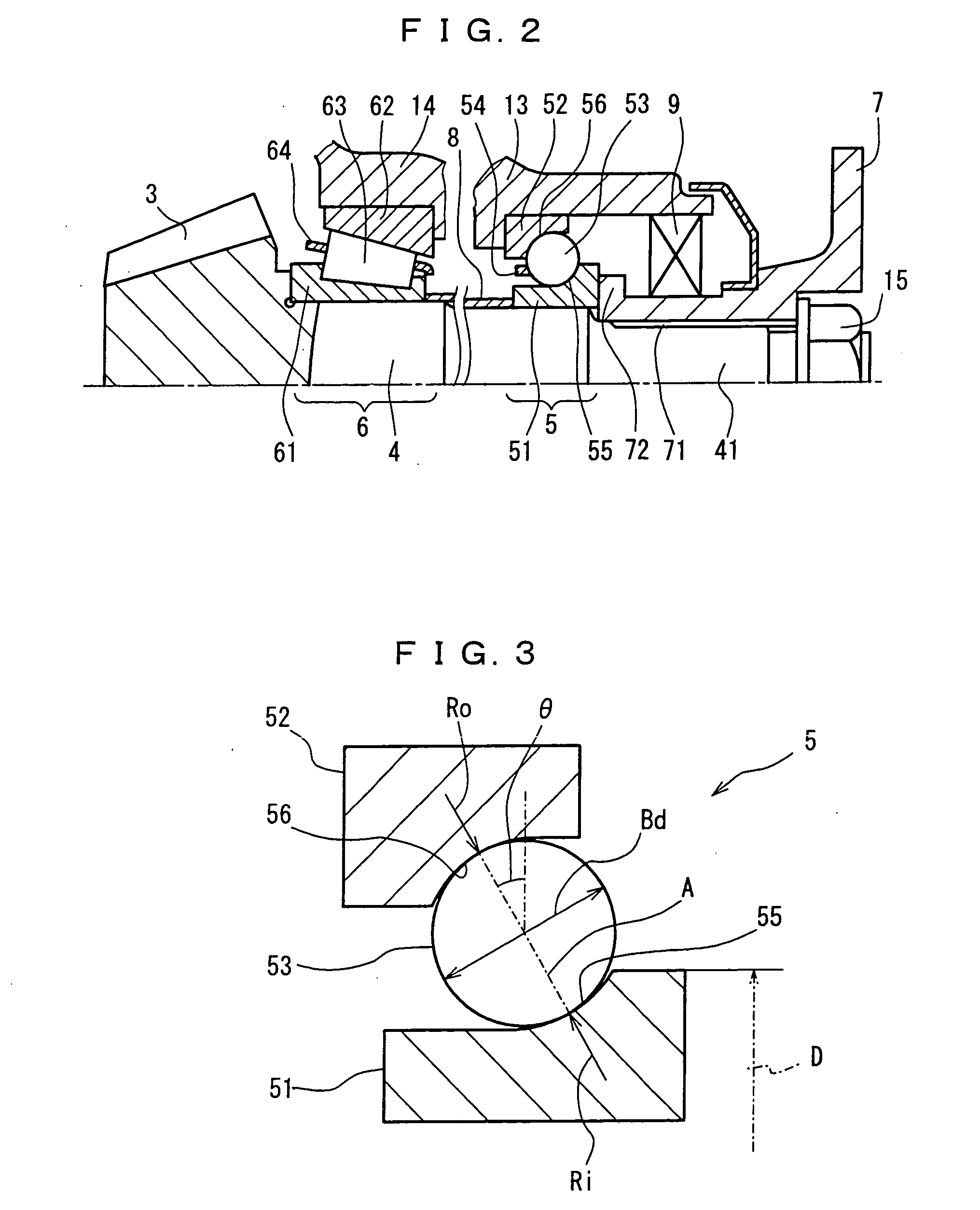
[0051] The bearing apparatus for supporting the pinion shaft of this second embodiment is characterized in that the rolling bearing 5 on the companion flange side comprises the angular contact ball bearing with single raceway, the rolling bearing 6 on the pinion gear side comprises the tandem type angular contact ball bearing with double raceway, and grease G is filled in a space between the rolling bearings 5 ands 6.

[0052] Incidentally, since the other configurations are similar to t...

third embodiment

[0074] Description will be made of the present invention using FIG. 10 and FIG. 11.

[0075]FIG. 10 is a cross-sectional view of a differential mechanism to which a bearing apparatus for supporting a pinion shaft in the third embodiment is applied, and FIG. 11 shows a partially expanded cross-sectional view of the bearing apparatus for supporting the pinion shaft shown in FIG. 10.

[0076] The bearing apparatus for supporting the pinion shaft of this third embodiment is characterized in that the rolling bearing 5 on the companion flange side is comprised of the tandem type angular contact ball bearing with double raceway to be used as the angular ball bearing.

[0077] Incidentally, since the other configurations are similar to those of the example of FIG. 13, the same symbols are given the same components and description thereof will be omitted.

[0078] The rolling bearing 5 comprises the inner ring 51 having a pair of inner ring raceways 55 and 57, the outer ring 52 having a pair of outer...


PUM


Abstract

A bearing apparatus for supporting a pinion shaft comprises a pair of rolling bearings which rotatably support a pinion shaft to a case and are arranged side by side in a shaft direction between a pinion gear arranged at one end of the pinion shaft, and a companion flange attached outside the other end thereof. The rolling bearing on a companion flange side comprises an angular ball bearing, and a radius of curvature Ri of an inner ring raceway, a radius of curvature Ro of an outer ring raceway, and a ball diameter Bd of the rolling bearing may satisfy a relationship given by equations of Ri<Ro, 0.502×Bd≦Ri≦0.512×Bd, and 0.510×Bd≦Ro≦0.520×Bd.

Description

FIELD OF THE INVENTION [0001] The present invention relates to a bearing apparatus for supporting a pinion shaft for rotatably supporting a pinion shaft which configures a differential mechanism of a vehicle, a transfer mechanism for a four-wheel drive vehicle, or the like. DESCRIPTION OF THE PRIOR ART [0002] In a differential mechanism of a vehicle, or a transfer mechanism for a four-wheel drive vehicle, there has been conventionally proposed a configuration where a pinion shaft has been rotatably supported by a tapered roller bearing at a pinion gear side and a companion flange side, respectively (For example, refer to Japanese Patent Application Publication No. 9-105450 and 10-220468). In the case of such differential mechanism and transfer mechanism, a tapered roller bearing with large load carrying capacity is used for a rolling bearing on a pinion gear side or a companion flange side. [0003] When the tapered roller bearing with large load carrying capacity is used, frictional ...

Claims


Application Information

Patent Timeline
IPC IPC(8): F16C19/49F16C33/58F16C19/16F16C19/18F16C19/54F16C33/78F16C35/06F16H48/42F16H57/021F16H57/037
CPCF16C19/163F16C19/182F16C19/54F16C33/7869F16C35/06F16C2240/80F16H57/021F16H57/037F16H2048/423F16C2361/61F16C19/184F16C19/548
Inventor KAWAMURA, MOTOSHIAKIYAMA, MUNEYASUTACHI, HIROSHI
Owner JTEKT CORP
Why Eureka
Try Eureka