
Eureka
For R&D, Eureka makes reading and utilizing patents & technical documents easy.
Eureka AIR
Designed for self-driven R&D workflows. Generate viable solutions, solve complex R&D challenges, empower your innovation with AI.

Eureka Materials
Designed for material experts only. Revolutionize your material R&D, from search, analyze, to developing new materials.

TechResearch
Generate reliable direction feasibility study reports for your R&D in just a few steps.

TechSeek
Discover and master advanced knowledge NOW. Basics, ideas, possibilities, all at once.

TechMind
As an expert in R&D Theories, TechMind can generates customized viable solutions instantly.

TechRisk
Analyze your overall solution with one click, know your potential R&D risks in advance.

TechMonitor
Get weekly tech updates, stay abreast of the latest tech innovations and key insights.
Method and Apparatus for Recording and Playing Back Monitored Video Data
- Summary
- Abstract
- Description
- Claims
- Application Information
AI Technical Summary
Benefits of technology
Problems solved by technology
Method used
Image

Examples
first embodiment
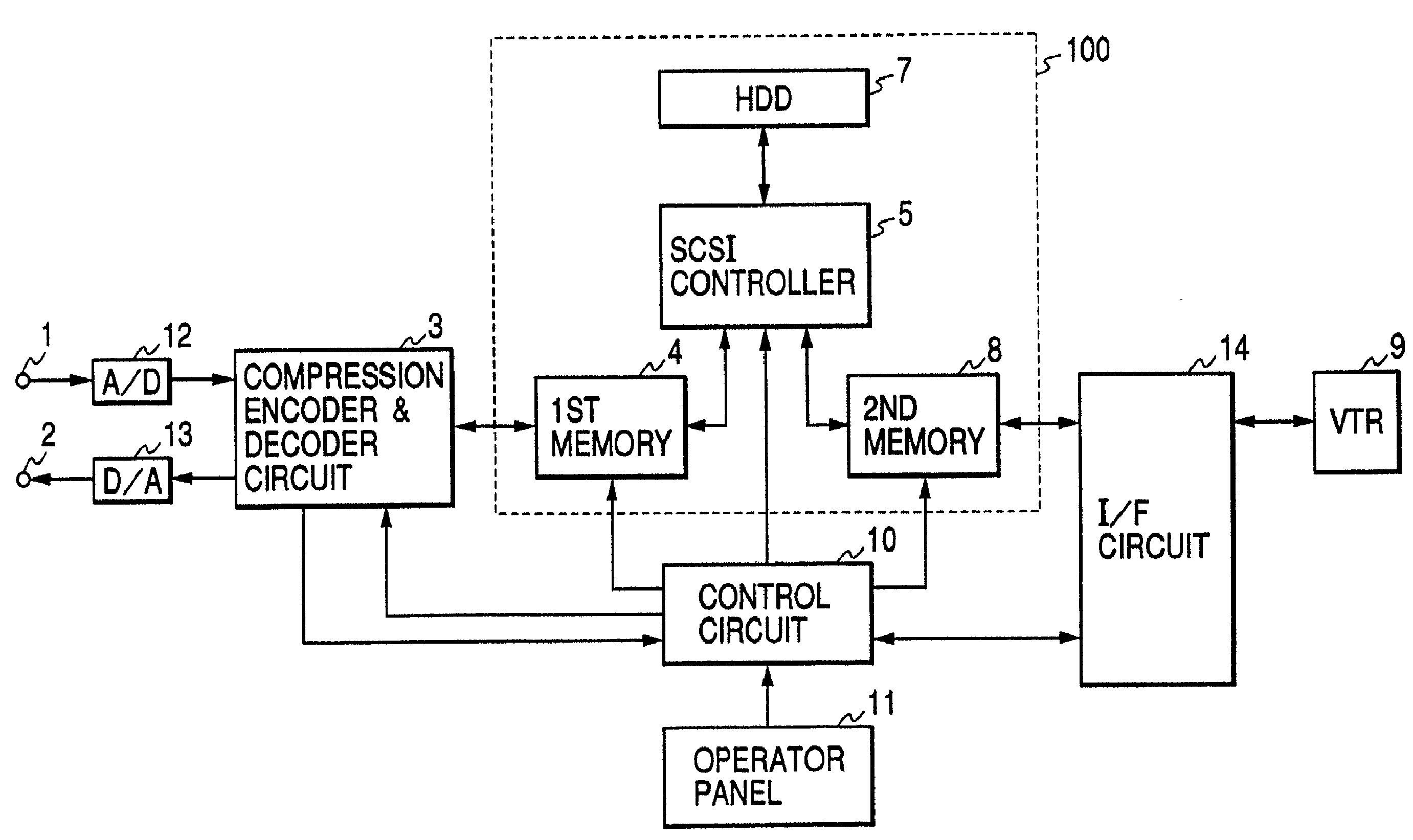
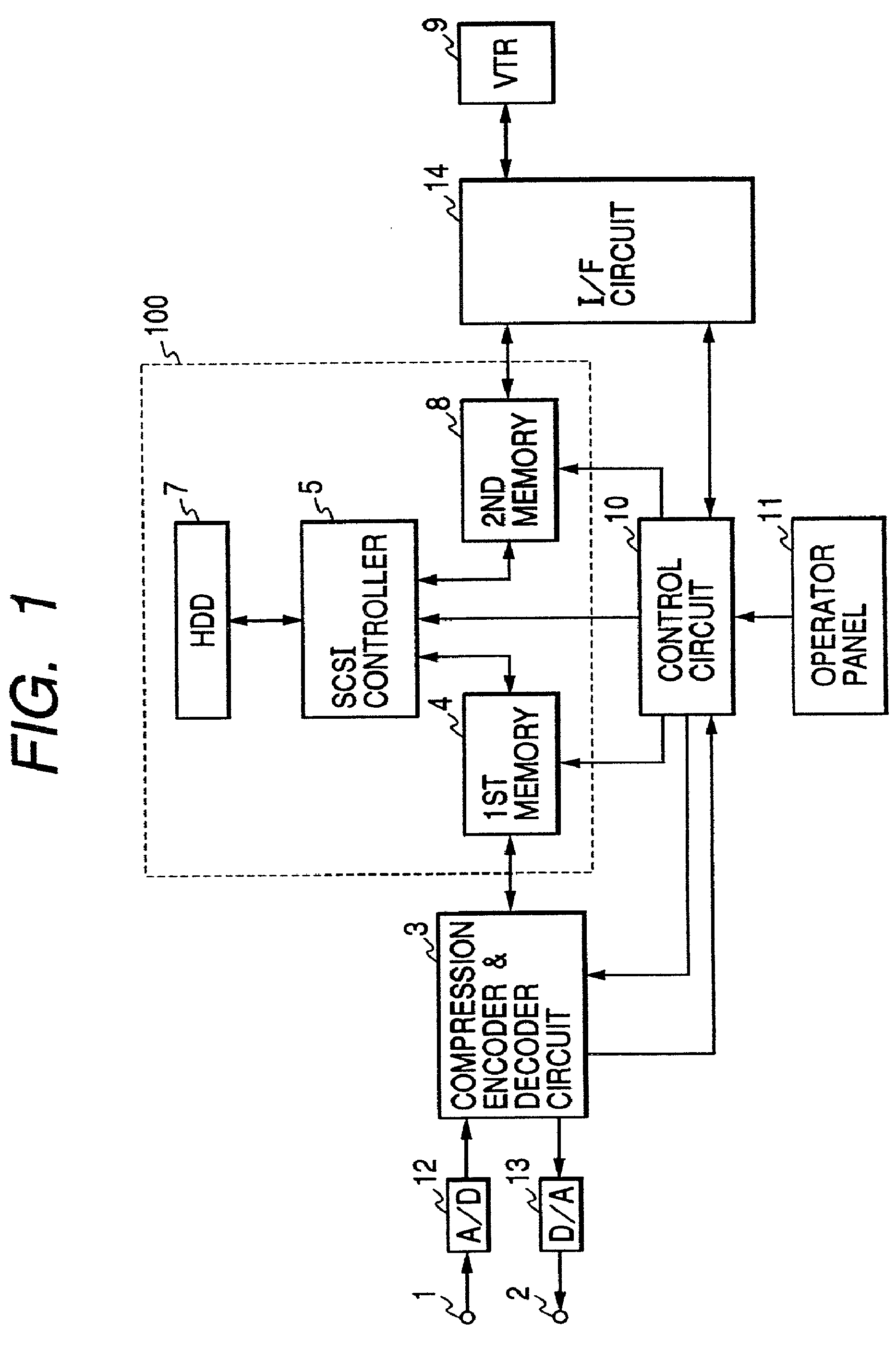
[0033]FIG. 1 is a block diagram of the recording & playback apparatus for monitored video data in the present invention. In FIG. 1, numeral 1 indicates a terminal to input video signals from a video camera (not illustrated), 2 indicates a terminal to output video signals, 3 indicates a compression encoder & decoder circuit, 4 and 8 indicate semiconductor memories (4: the first memory, 8: the second memory), 5 indicates an SCSI (Small Computer System Interface) controller, 7 indicates a hard disk unit (hereafter, to be abbreviated as HDD) provided with an SCSI interface, 9 indicates a VTR, 10 indicates a control circuit, 11 indicates an operator panel from which the operator instructs various operations, 12 indicates an A / D converter, 13 indicates a D / A converter, and 14 indicates an IEEE1394 interface circuit (hereafter, to be abbreviated as I / F circuit). Of those devices, the semiconductor memories (the first and second memories 4 and 8), the SCSI controller 5, the HDD 7 are combin...
second embodiment
[0080] Subsequently, the monitored video data recording & playback apparatus in the present invention will be explained.
[0081] In this second embodiment, the input video data time axis is thinned out to record video data at a smaller rate and enable super-long time continuous recording of video data.
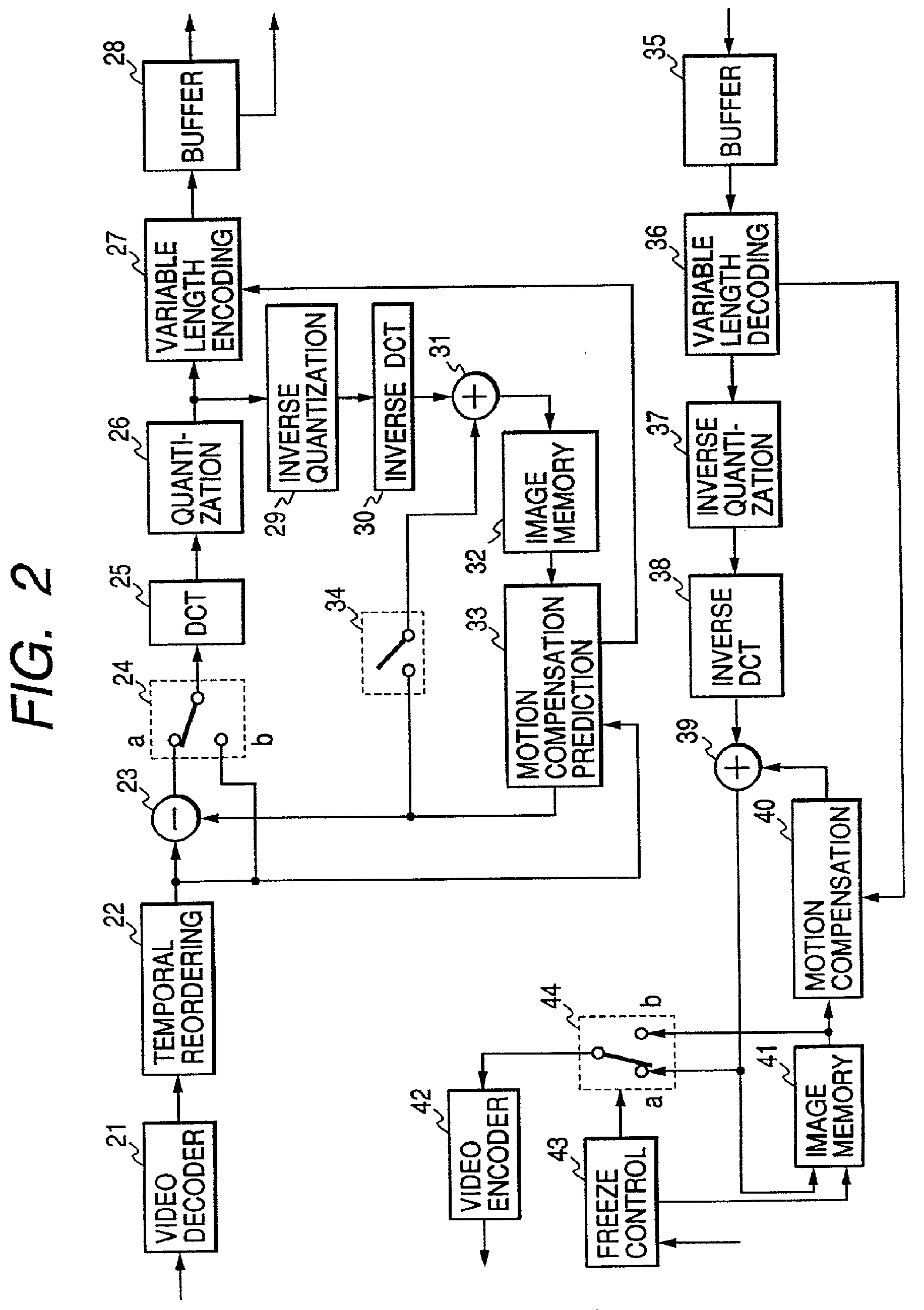
[0082] At first, FIG. 6 is a block diagram of the compression encoder & decoder circuit (refer to 3 in FIG. 1, and FIG. 2) to thin out the above time axis. This compression encoder & decoder circuit differs from the compression encoder & decoder circuit 3 shown in FIG. 2 in that a thinning-out circuit 45 is added and the speed of the compression encoding main processor (enclosed by a broken line) operation can be changed according to the mode signal from the thinning-out circuit 45. This thinning-out circuit 45 writes the frame period of video data from the decoder 21 in a memory and reads the data from the memory for a k-frame period at a reading rate of 1 / k (k=a natural number of 2 or...
fourth embodiment
[0096] Hereunder, another embodiment of the present invention will further be explained. FIG. 11 is a block diagram of the monitored video data recording & playback apparatus in the present invention. In FIG. 11, numeral 18 indicates a data sorting circuit and 19 indicates a control circuit. Other items given the same numerals as those in FIG. 1 are the same as those in FIG. 1.
[0097]FIG. 12 is a block diagram indicating the configuration of the data sorting circuit 18. In FIG. 12, numeral 101 indicates a type judgement circuit, 102, 103, 109, and 110 indicate FIFO memories, 104 and 111 indicate memory control circuits, 105 indicates an order code adding circuit, 106 and 107 indicate FIFO buffers, 108 indicates a code decision circuit, 112 and 114 indicate switch circuits, and 113 indicates an order code deletion circuit.
[0098] In the configuration of the above data sorting circuit 18, the type decision circuit 101 detects the sync code (Picture Start Code to be abbreviated as PST) ...
PUM
 Abstract
Description
Claims
Application Information
 - R&D Engineer
- R&D Manager
- IP Professional
- Industry Leading Data Capabilities
- Powerful AI technology
- Patent DNA Extraction
Browse by: Latest US Patents, China's latest patents, Technical Efficacy Thesaurus, Application Domain, Technology Topic, Popular Technical Reports.
© 2024 PatSnap. All rights reserved.Legal|Privacy policy|Modern Slavery Act Transparency Statement|Sitemap|About US| Contact US: help@patsnap.com