Laminant hot runner manifold

a hot runner and manifold technology, applied in the field of hot runner manifolds, can solve the problems of difficulty in cleaning the manifold after molding process, difficulty in grinding or smoothing the interior of the flow channel, and difficulty in ensuring the quality of finished products or in cleaning the manifold after completion of molding process, so as to improve the processing of plastic materials, improve the holding strength of cross pins, and improve the effect of welding or bolting the two pieces together

Inactive Publication Date: 2007-05-10
INCOE CORP
View PDF7 Cites 10 Cited by
  • Summary
  • Abstract
  • Description
  • Claims
  • Application Information

AI Technical Summary

Benefits of technology

[0011] When cross-pin members are utilized, it is also possible to utilize pin members with a different coefficient of expansion or expansion rate than the material used for the manifold members. As a result, increased expansion of the cross-pin members will increase the holding strength of the cross pins and further aid in securely holding the two mold members

Problems solved by technology

It is difficult to grind or smooth the interior of flow channel holes bored by gun drills, however, and the corners formed at junctions where two or more bored holes meet create additional problems.
Sharply angled corners hinder the smooth flow of the plastic materials and any imperfections or defects in the smoothness of the flow channels can create distress in the material and may retain remnants of material creating difficulties in either the quality of the finished products or in cleaning the manifold after completion of the molding process.
Problems have developed with two-piece manifolds relative to securely holdi

Method used


Image

  • Laminant hot runner manifold
  • Laminant hot runner manifold
  • Laminant hot runner manifold

Examples


Embodiment Construction

(s)

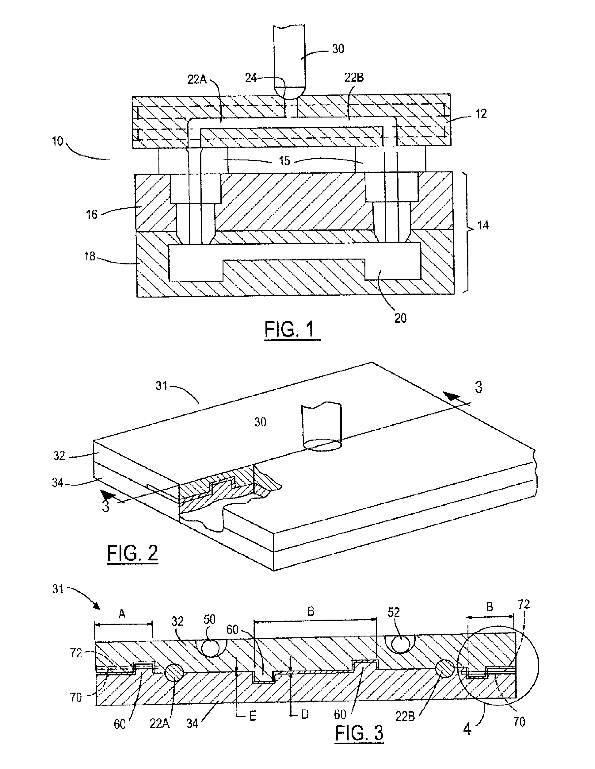
[0021]FIG. 1 is a schematic diagram of a conventional plastic injection molding system 10 which illustrates some of the basic components utilized with the present invention. Plastic injection molding processes are used to mold plastic products and components that are in wide use today. In such processes, the plastic material is melted in an injection molding machine and then injected from the machine through a nozzle into a cavity in a mold or tool. The mold cavity is formed or machined in the shape of the part or component to be produced. The plastic material is typically injected through a bushing or nozzle into the mold cavity. The mold or tool itself is cooled by conventional cooling means in order to harden the plastic material once the mold cavity is filled.

[0022] Once the plastic material in the mold cavity is cooled and hardened sufficiently to be self-supporting, the mold is opened and the part is removed. Thereafter, the mold is closed and another cycle is initiated.

[...


PUM

PropertyMeasurementUnit
Lengthaaaaaaaaaa
Flow rateaaaaaaaaaa
Areaaaaaaaaaaa

Abstract

A two-piece hot runner manifold with plastic flow channels formed as recesses in the two mating surfaces. One or more mating structures, such as posts and sockets, ridge and groove configurations, or the like, are provided along the mating surfaces of the two mating manifold members. A bonding material, such as bronze, can be used to hold the two pieces of the hot runner manifold together. Cross pin members are preferred for use in securing the two mating manifold members together.

Description

TECHNICAL FIELD [0001] The present invention relates to hot runner manifolds used in plastic injection molding, and more particularly to improved two-piece hot runner manifolds. BACKGROUND OF THE INVENTION [0002] Hot runner manifolds are commonly used in the injection molding of plastic materials. The manifolds are used to transport the molten plastic material from an injection molding machine to various bushings or nozzle drops. The manifolds have passageways or channels in them for transport of the molten plastic material to the bushings or nozzles, and finally to the mold cavity. Heater members, or elements, are contained within or on the manifold and maintain the plastic material in the manifold at the requisite temperature for molding. [0003] Conventional manifolds typically are made from a single block or piece of metal material. The channels or passageways in these manifolds are typically formed by drilling, such as by use of a gun drill. It is difficult to grind or smooth th...

Claims


Application Information

Patent Timeline
IPC IPC(8): B29C45/00
CPCB29C45/2725
Inventor BLUNDY, JOHN D.
Owner INCOE CORP
Why Eureka
Try Eureka