Elongate spring member having bushing mounts with improved bushing retention characteristics

Inactive Publication Date: 2007-05-17
STANDENS
View PDF6 Cites 14 Cited by
  • Summary
  • Abstract
  • Description
  • Claims
  • Application Information

AI Technical Summary

Benefits of technology

[0033] Securely housed between the ridges, a bushing without an external metal sleeve or bonding compound can be retained in the bushing mount. Without the stress exerted on the bushings by an interfe

Problems solved by technology

The open ends of these standard rolled mounts tend to open further during deformation caused by excessive loading.
This deformation changes the size and shape of the eye so that the bushing is no longer properly seated and firmly secured therein.
As a result of the interference fit, the bushing is under stress immediately upon installation, which increases the rate of wear.
Bonding compounds are expensive and susceptible to damage due to environmental conditions such as temperature extremes and che

Method used


Image

  • Elongate spring member having bushing mounts with improved bushing retention characteristics
  • Elongate spring member having bushing mounts with improved bushing retention characteristics
  • Elongate spring member having bushing mounts with improved bushing retention characteristics

Examples


first embodiment

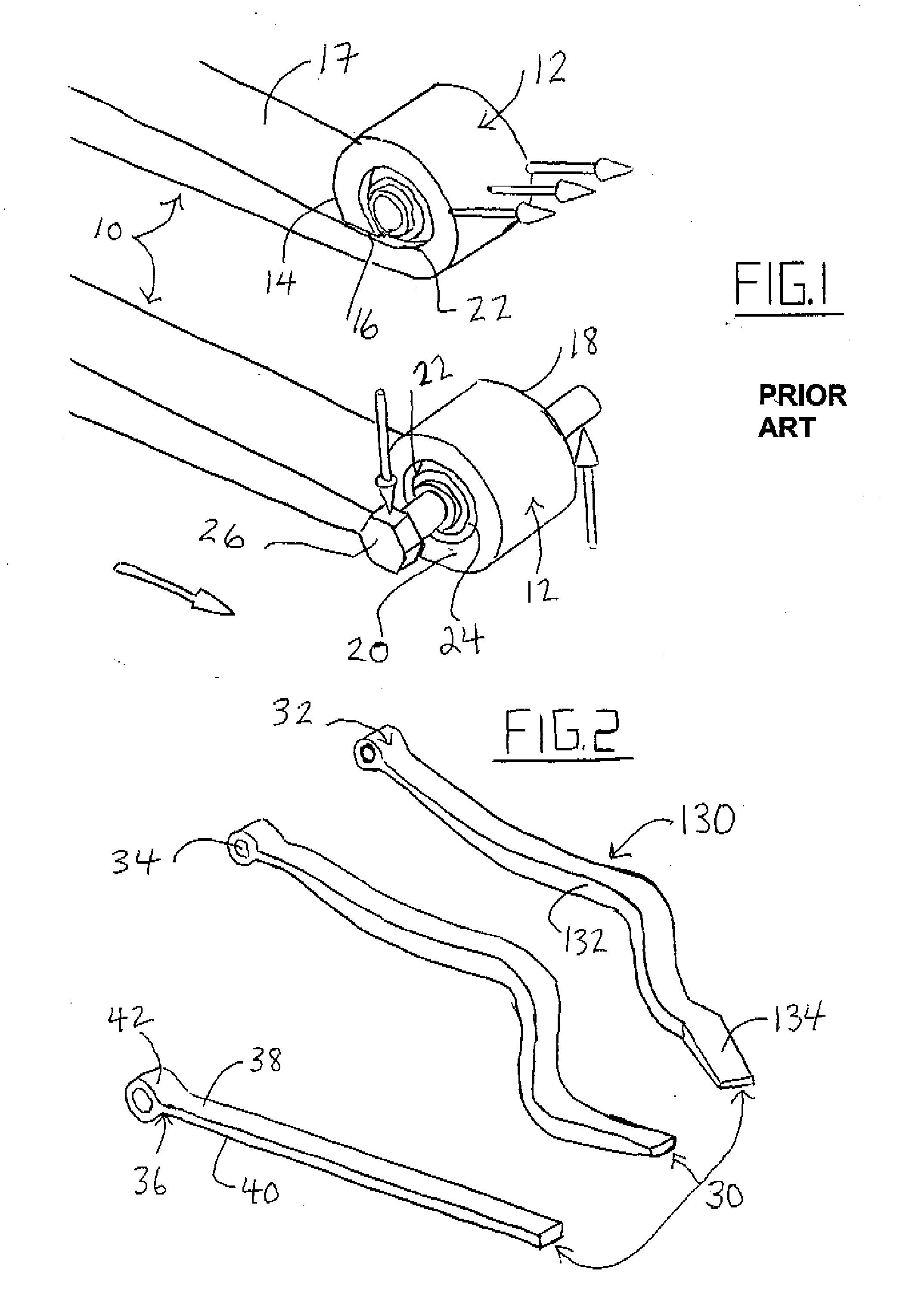
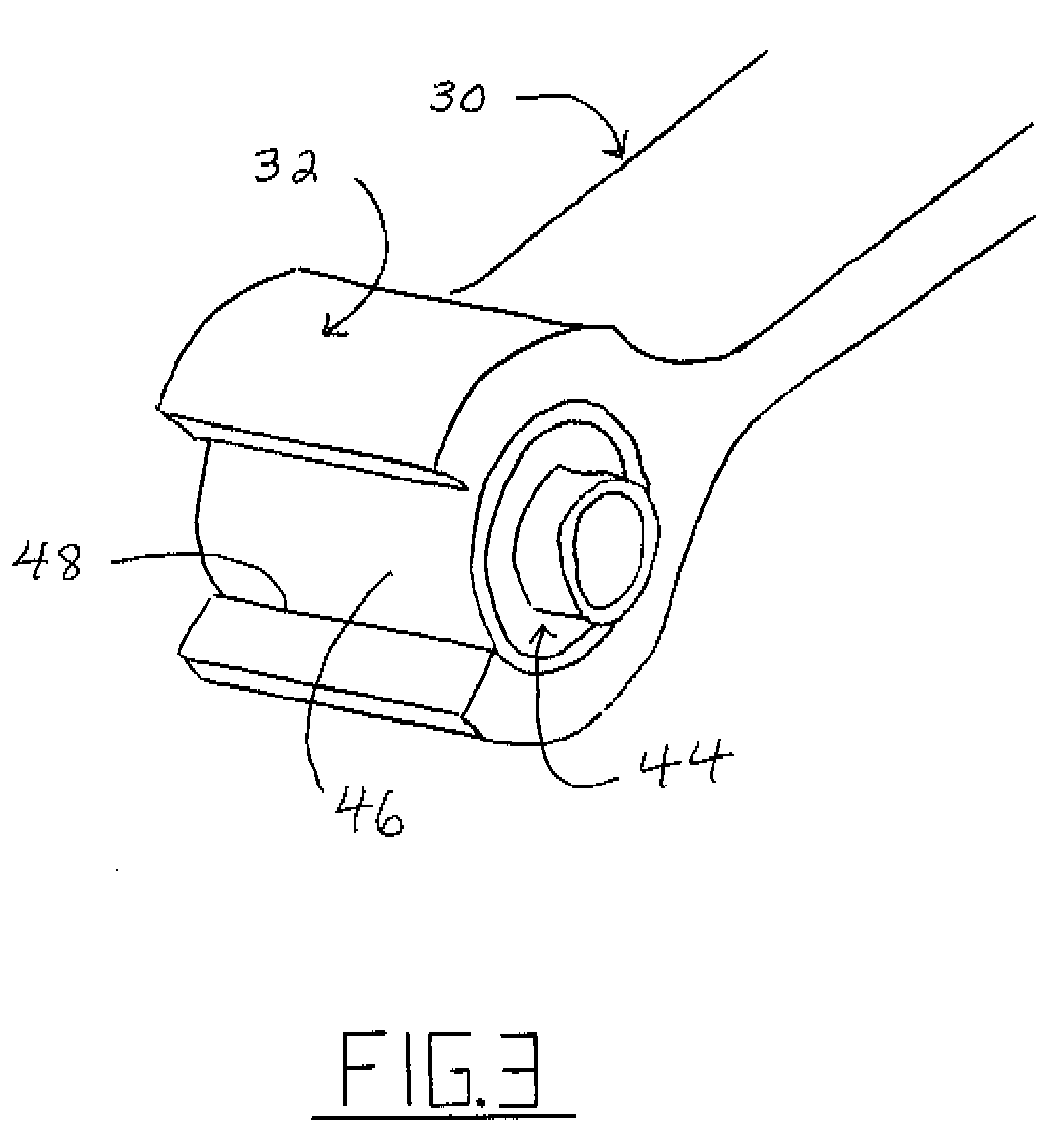
[0073]FIG. 2 shows three spring beams 30 commonly used in suspension systems: a straight beam, a Z-beam and a twisted Z-beam. Each beam 30 features a bushing mount 32 according to the present invention. These beams do not feature the open rolled ends 14 of the prior art beams 10 of FIG. 1 and therefore do not have the gaps 16 between the end and the upper surface 17 of the beam. Instead, the bushing mounts 32 are formed integrally with the beams 30 by a forging process to define and endless loop extending the full width of each spring member at its mounting end. Forming such a beam involves forging an end of an elongate spring member to form a mounting element integral with the spring member and having a cylindrical inner surface defining a cylindrical opening extending transverse to the elongate member, the inner surface being endless about the cylindrical opening and continuous from one end of the opening to the other. As a result, the cylindrical opening 34 is completely enclosed...

second embodiment

[0079] The ridges, or lips, at the ends of the bushing mount of the second embodiment encapsulate the bushing to withstand lateral loads transmitted by a suspension system. Without the stress induced by an interference fit between the mount and an externally sleeved bushing, the life of the bushing is improved. Also, the use of costly, condition sensitive bonding compounds is avoided. It should be appreciated that reducing the number of components required in the suspension assembly also reduces the number of variables involved in its function and / or failure. In this case, a three part combination of a bushing, a spring beam and a retaining component therebetween (for example, a sleeve or bonding compound) has been reduced to a two part combination of a bushing and a spring beam. Bushings are installed into the ridged bushing mount 60 with the aid of a tapered installation sleeve or shallow funnel. Bushings are generally only removed after failure, in which case the bushings would b...

third embodiment

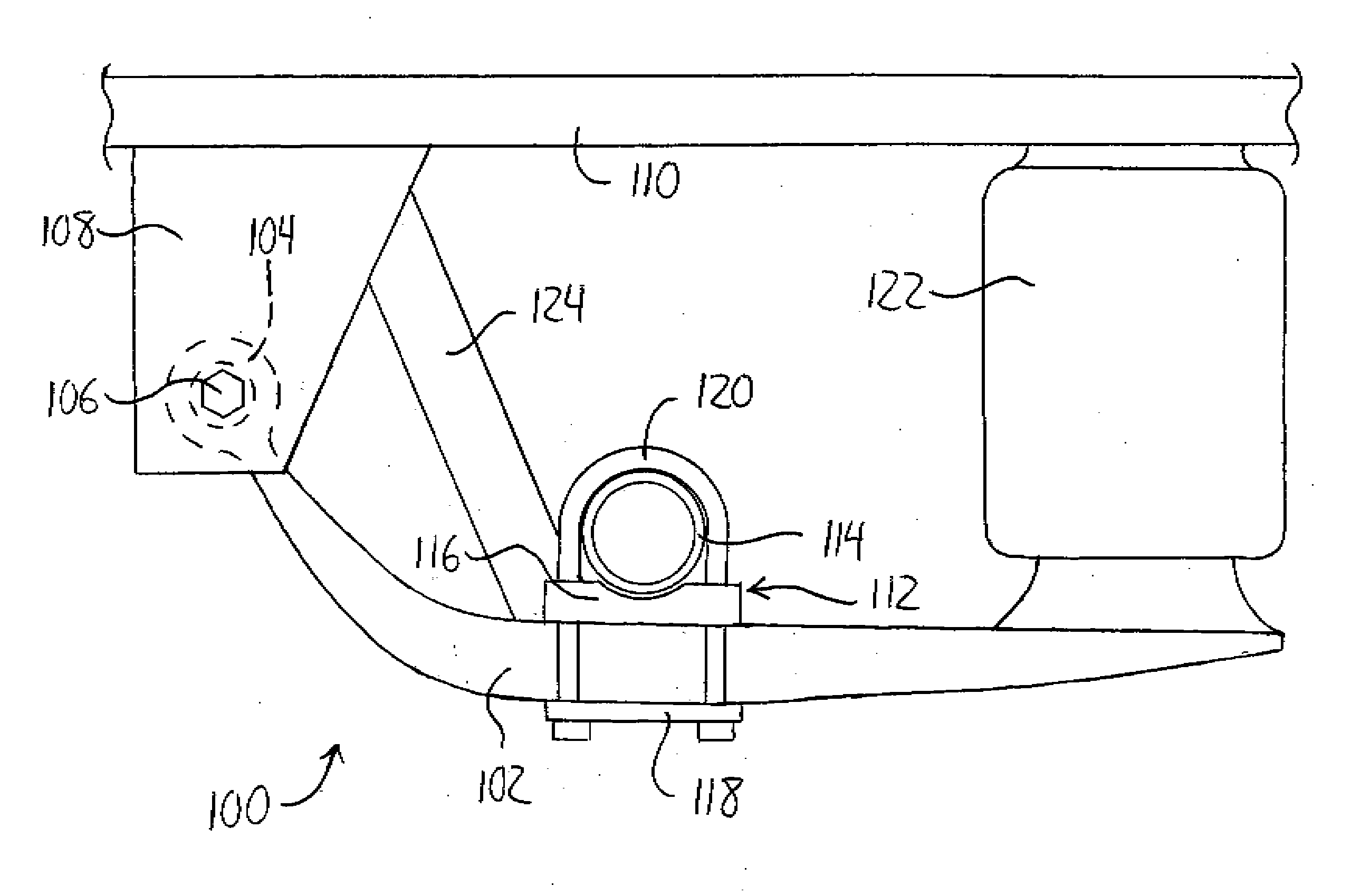
[0082]FIG. 8 shows an air suspension system 100 using a spring member 102, having a mounting element 104 configured in accordance with the mounting elements of the first or third embodiment, cooperating with conventional air suspension components. A bushing is fitted within the mounting element 104 as described and has a pin 106 extending through it to pivotally support the spring member 102 on a hanger 108 depending downward from a frame 110 of a vehicle. Between the ends of the spring member 102 is a coupling 112 securing an axle 114 of the vehicle to the spring member thereabove. The coupling 112 features an axle seat 116 contoured to receive the axle 114 and disposed atop the spring member and a respective mounting plate 118 disposed immediately beneath the spring member. U-bolts 120 extend about the top of the axle 114 and extend downward through the axle seat 116 on opposite sides of the spring member 102 to engage the mounting plate 118 disposed therebeneath. The coupling thu...


PUM


Abstract

Cylindrical bushing mounts, or eyes, for spring members have improved bushing retention characteristics over conventional mounts. In a first embodiment, a spring member has a bushing mount formed by forging to be integral with the spring beam and define an endless loop that fully encloses a cylindrical opening for receiving a bushing. The integral mount better resists deformation under loading than typical rolled mounts having an open end, and therefore can be made having a thinner cross section to reduce the weight of the beam. In a second embodiment, a spring member features a rolled mount having a profiled inner surface defining ridges protruding inward at each end of the mount's cylindrical opening. A bushing received in the mount is housed between the ridges, eliminating the need for an interference fit or bonding compound to retain the bushing.

Description

[0001] This application claims the benefit under 35 U.S.C.119(e) of U.S. provisional application Ser. No. 60 / 728,802, filed Oct. 21, 2005.FIELD OF THE INVENTION [0002] This invention relates to spring members having bushing mounts, and more particularly to a spring members having bushing mounts with improved bushing retention characteristics. BACKGROUND OF THE INVENTION [0003] Elongate spring members, such as leaf springs and spring beams, are often used in vehicle suspension systems designed to resiliently connect a vehicle's axle(s) to its frame. However such spring members can be used in many different situations and the present invention is applicable to any of these and is not intended to be limited to vehicle suspensions. [0004] An example of an application for elongate spring members relates to air bag suspension systems, which are applied in great number to heavy truck fleets utilized in the transport industry. Air suspensions for large commercial trucks are used for on and ...

Claims


Application Information

Patent Timeline
IPC IPC(8): B60G11/00F16F1/26
CPCB60G9/003B60G11/465B60G2200/31B60G2202/112B60G2202/152B60G2204/121B60G2204/41B60G2204/4108B60G2206/15F16F1/28
Inventor STOESZ, DONALDSVENDSEN, MELVIN
Owner STANDENS
Why Eureka
Try Eureka