Image recognition system and use thereof

Inactive Publication Date: 2007-05-17
FRAUNHOFER GESELLSCHAFT ZUR FOERDERUNG DER ANGEWANDTEN FORSCHUNG EV
View PDF23 Cites 126 Cited by
  • Summary
  • Abstract
  • Description
  • Claims
  • Application Information

AI Technical Summary

Benefits of technology

[0011] Starting from these disadvantages of the state of the art, it is the object of the present invention to provide an image recognition system which has

Problems solved by technology

The field of view of the arrangement is limited by the maximum possible pitch difference between lens array and pinhole array.
However, this is entirely inconsistent with the system integration which is sought.
Because of the same pitch of lens array and pinhole array, a resolution of the object is no longer possible for fairly large object distances with this arrangement.
However this is inconsistent with the aim of integration.
The pinhole diameters which are used are 140 μm which does not permit good resolution of the system.
Hence, individually produced components here are also adjusted

Method used


Image

  • Image recognition system and use thereof
  • Image recognition system and use thereof
  • Image recognition system and use thereof

Examples


Embodiment Construction

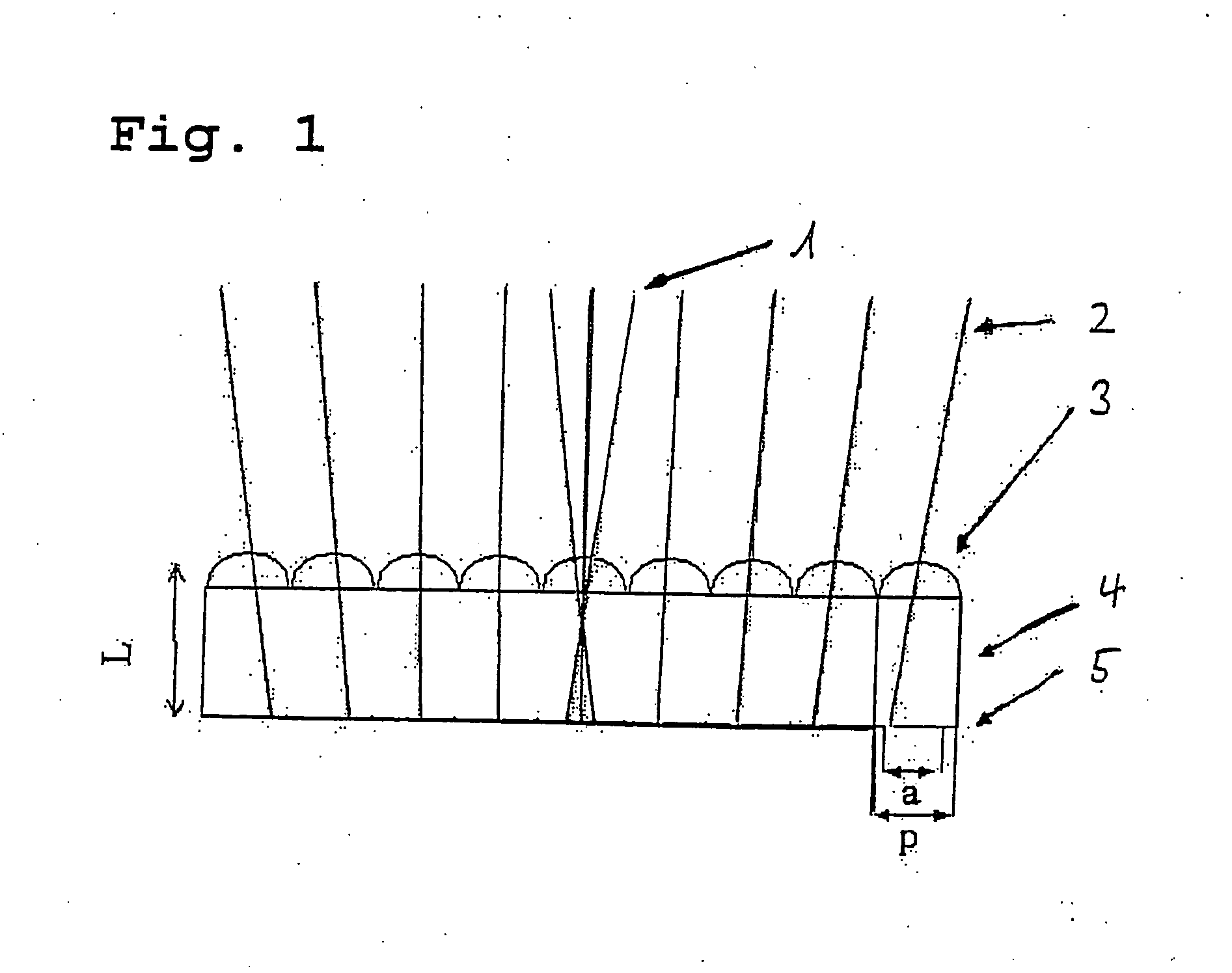
[0105]FIG. 1 shows a variant of the subject according to the invention. In FIG. 1 the following reference numerals mean: 1, Acceptance of an optical channel (Δφ); 2, Sampling of the FOV (sampling angle ΔΦ); 3, Lens array, lenses with diameter D and focal distance f are centred in cells with pitch p; 4, Substrate; and 5, Pinhole array (in metal layer), pinhole offset in cells determines viewing direction, diameter of the pinhole d determines acceptance angle Δφ

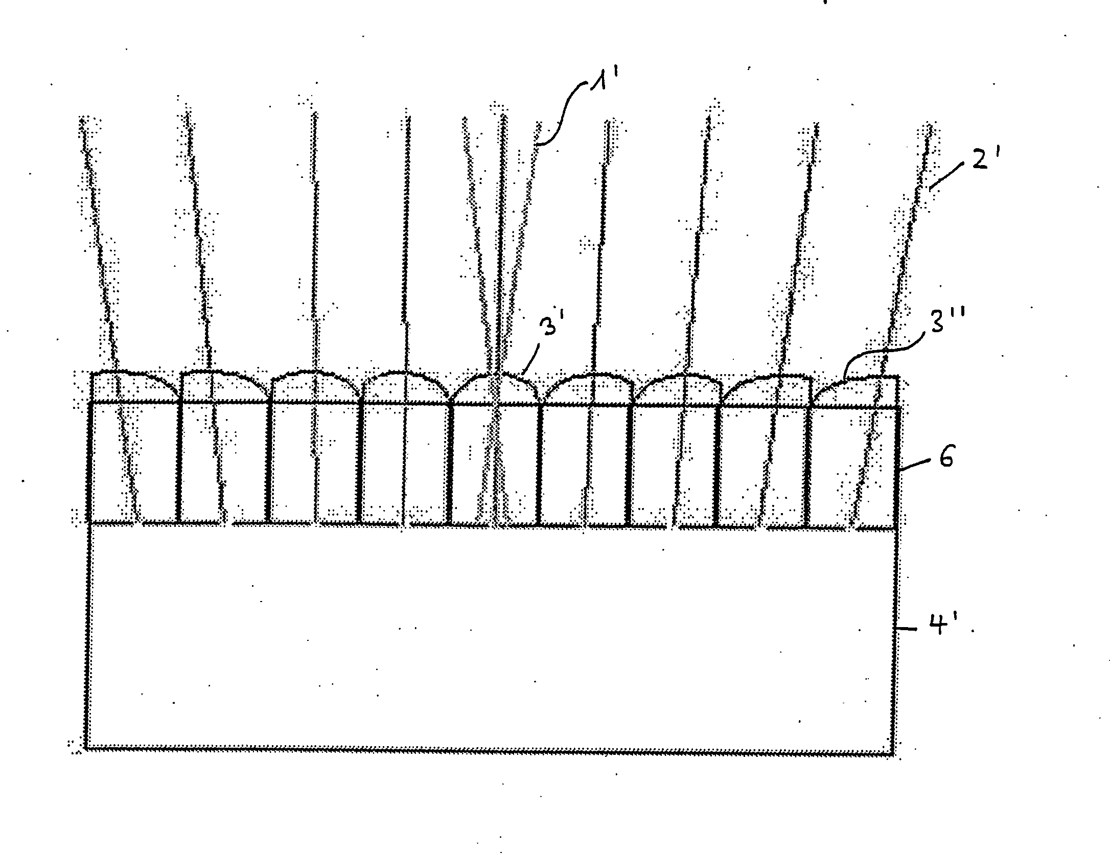
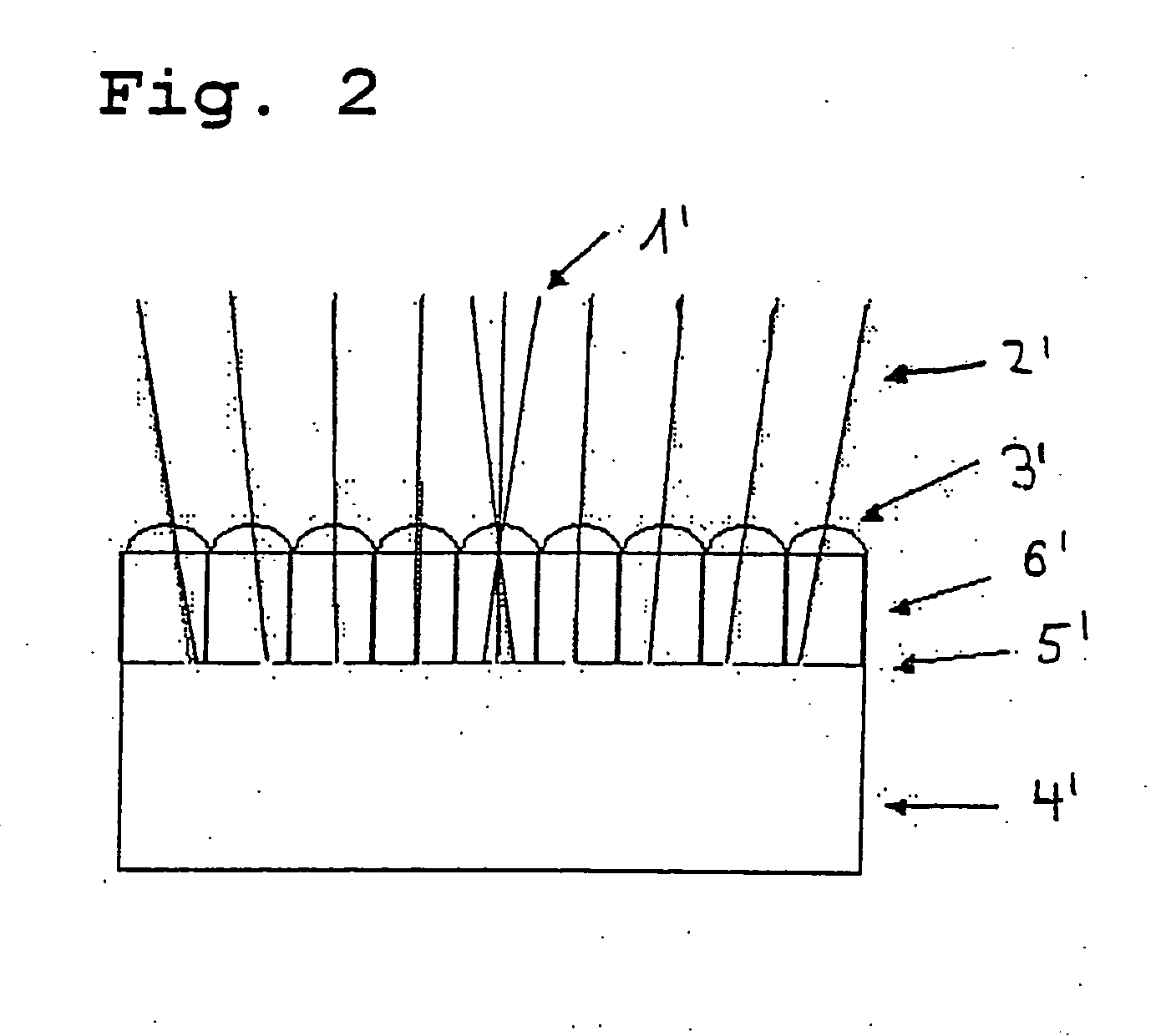
[0106] Optical axes which can be produced in different ways (hereby pitch difference of the microlens array and the pinhole array) and which increase outwards in inclination in order to achieve the (negative) enlarged imaging mean that a source in the object distribution delivers only one signal in a corresponding photosensitive pixel if it is located on or near to the optical axis of the corresponding optical channel. If the source point is moved away from the considered optical axis, then the signal of the corresponding detec...


PUM


Abstract

The present invention relates to a digital image recognition system having a minimum constructional length of less than one millimetre. The image recognition system hereby comprises a microlens array, a detector array and optionally a pinhole array. The mode of operation of this image recognition system is based on a separate imaging of different solid angle segments of the object space by means of a multiplicity of parallel optical channels. The optical axes of the individual optical channels thereby have different inclinations so that they represent a function of the distance of the optical channel from the centre of the side of the image recognition system orientated towards the image, as a result of which the ratio of the size of the field of view to the image field size can be determined specifically. Detectors are thereby used with such high sensitivity that the detectors have a large pitch with a small active surface area.

Description

BACKGROUND [0001] The invention relates to a digital image recognition system with a minimum constructional length of less than 1 mm. The image recognition system hereby comprises a microlens array, a detector array and optionally a pinhole array. The mode of operation of this image recognition system is based on a separate imaging of different solid angle segments of the object space by means of a multiplicity of parallel optical channels. [0002] In the case of classic imaging optical systems, an individual optical channel (objective) images all the information from the object space into the image plane. The objective images the entire detectable angle range of the object space. [0003] In S. Ogata, J. Ishida and T. Sasano, “Optical Sensor Array in an artificial compound eye”, Opt. Eng. 33, pp. 3649-3655, November 1994, an optical sensor array is presented. The optical correlations for such a general system are represented in detail. Association of the microoptics with photoelectric...

Claims


Application Information

Patent Timeline
IPC IPC(8): G02B13/16G02B3/00G02B13/00G02B27/09H04N5/225H04N5/335
CPCG02B3/0012G02B3/0043G02B3/0056G02B3/0075G02B13/0055H04N5/2254H04N5/335G06K9/00046G06V40/1324H04N23/55H04N25/00
Inventor DUPARRE, JACQUESDANNBERG, PETERSCHREIBER, PETERVOLKEL, REINHARDBRAUER, ANDREAS
Owner FRAUNHOFER GESELLSCHAFT ZUR FOERDERUNG DER ANGEWANDTEN FORSCHUNG EV
Why Eureka
Try Eureka