Optical amplifier

a technology of optical amplifiers and amplifiers, applied in the field of optical amplifiers, can solve the problems of increasing the loss range, voa loss range, and affecting the performance of the optical amplifier, so as to increase the power of the ld

Active Publication Date: 2007-05-17
FUJITSU LTD
View PDF13 Cites 11 Cited by
  • Summary
  • Abstract
  • Description
  • Claims
  • Application Information

AI Technical Summary

Benefits of technology

[0024] In view of the foregoing, it is an object of the present invention to provide an optical amplifier which eliminates the need for an optical detection section before and after an external attenuating medium, does not cause SN degradation, and does not increase the power of the LD.

Problems solved by technology

The VOA loss range must be increased accordingly, but a great VOA loss range would worsen the noise factor.
If the optical detection section is provided before the variable optical attenuator and after the external attenuating medium, the varying amount of attenuation by the variable optical attenuator makes it impossible to check the connection or disconnection of the external attenuating medium in accordance with the correct amount of loss by the external attenuating medium.
The detection section provided before and after the external attenuating medium, however, requires that the signal light is branched into the detection section, and the loss depending on the branching ratio would lead to SN degradation.
This would reduce the cost effectiveness and would increase power consumption because of LD temperature control.

Method used


Image

  • Optical amplifier
  • Optical amplifier
  • Optical amplifier

Examples


first embodiment

[0051] the present invention will be described in detail with reference to drawings.

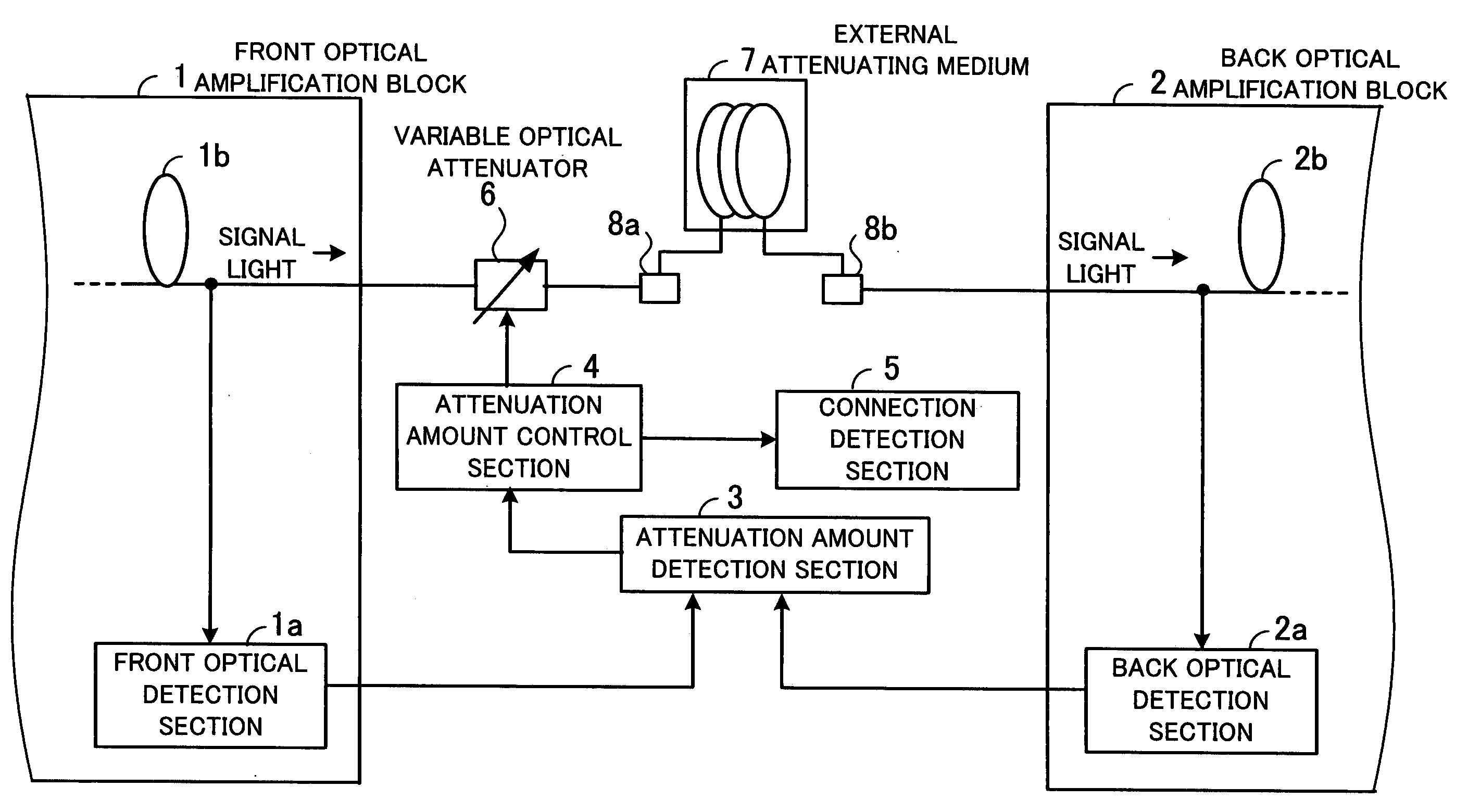
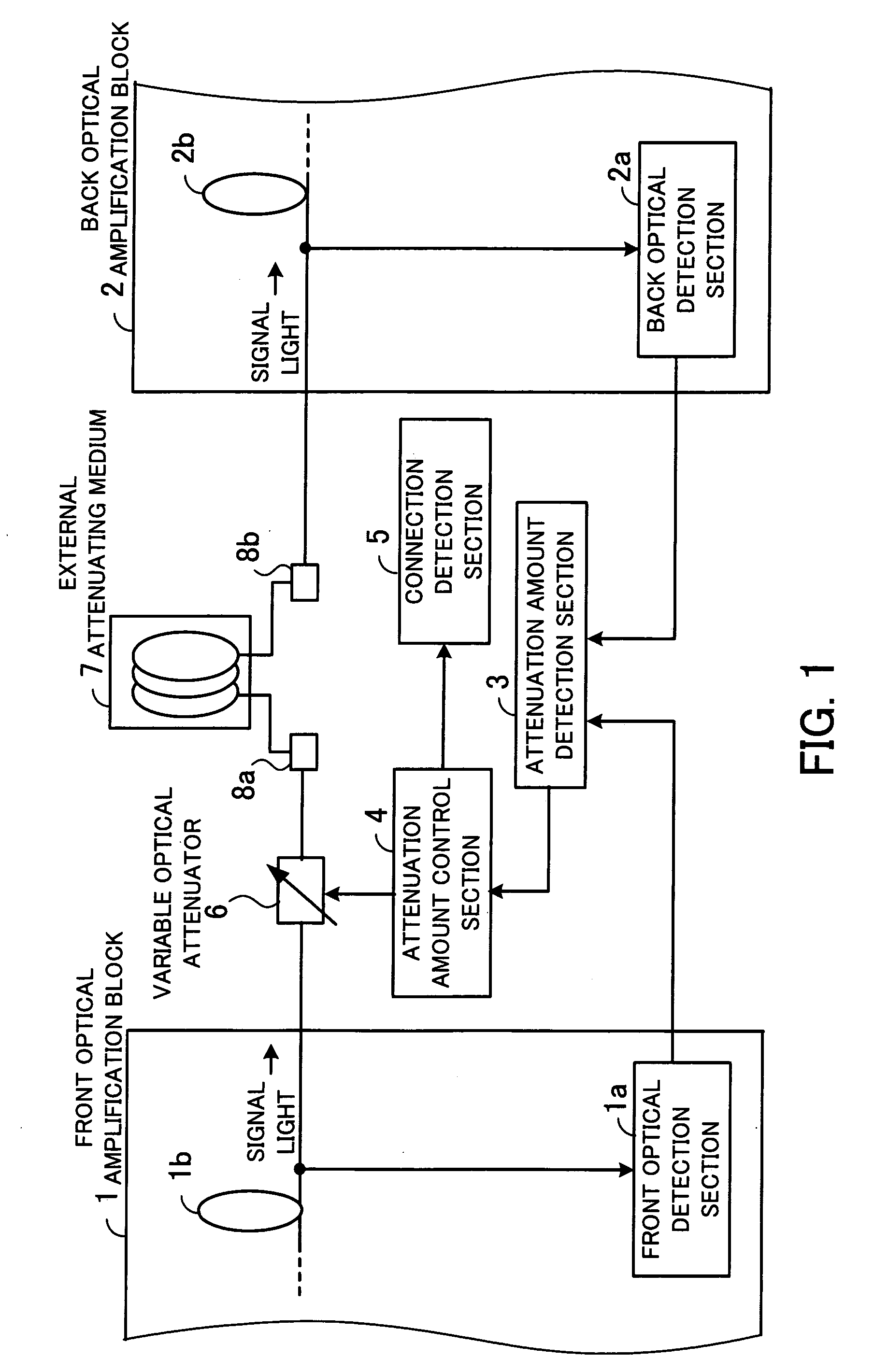
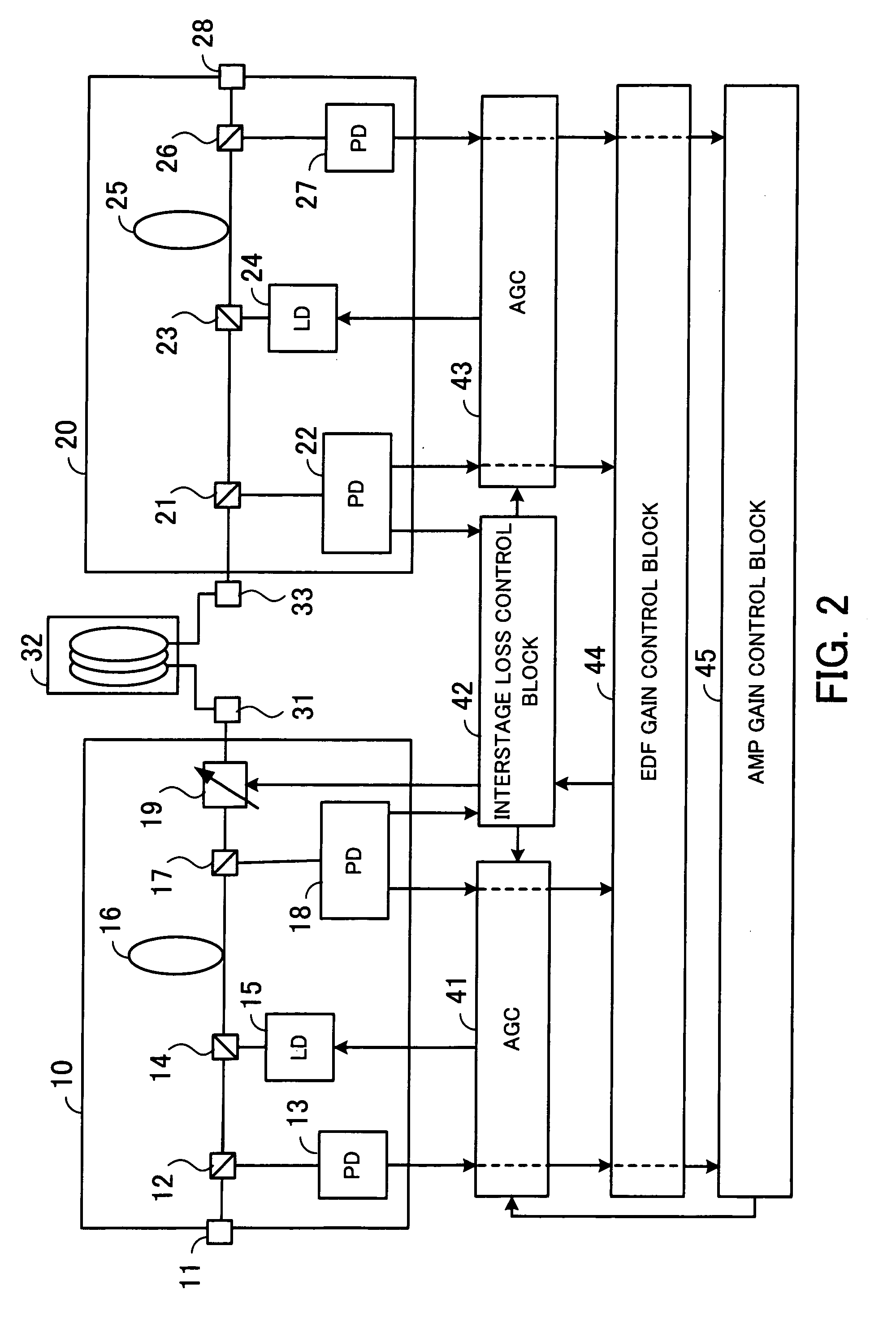
[0052]FIG. 2 is a block diagram of an optical amplifier of the first embodiment. As shown in the figure, the optical amplifier includes a front optical amplification block 10, a back optical amplification block 20, a DCF 32 connected to terminals 31 and 33, automatic gain controllers (AGCs) 41 and 43, an interstage loss control block 42, an EDF gain control block 44, and an AMP gain control block 45. The front optical amplification block 10 includes an input terminal 11, couplers 12, 14, and 17, PDs 13 and 18, an LD 15, an EDF 16, and a VOA 19. The back optical amplification block 20 includes couplers 21, 23, and 26, PDs 22 and 27, an LD 24, an EDF 25, and an output terminal 28.

[0053] The input terminal 11 of the front optical amplification block 10 receives wavelength division multiplexing (WDM) signal light, for instance. The signal light input to the input terminal 11 passes the couplers 12 and 1...

second embodiment

[0106]FIG. 8 is a block diagram of an optical amplifier of the As shown in the figure, the optical amplifier includes a front optical amplification block 50, a back optical amplification block 70, a DCF 82 connected to terminals 81 and 83, AGCs 91 and 93, an interstage loss control block 92, an EDF gain control block 94, a constant loss control block 95, and an AMP gain control block 96. The front optical amplification block 50 includes an input terminal 51, couplers 52, 54, 57, 60, 62, and 65, PDs 53, 58, 61, and 66, LDs 55 and 63, EDFs 56 and 64, and VOAs 59 and 67. The back optical amplification block 70 includes couplers 71, 73, and 76, PDs 72 and 77, an LD 74, an EDF 75, and an output terminal 78.

[0107] The input terminal 51 of the front optical amplification block 50 receives a WDM signal light, for instance. The signal light input to the input terminal 51 is output through the couplers 52 and 54 to the EDF 56. The signal input to the input terminal 51 is also branched off to...

third embodiment

[0162]FIG. 11 shows an optical amplifier of the As shown in the figure, the optical amplifier includes a front optical amplification block 140, a back optical amplification block 150, a DCF 172 connected to terminals 171 and 173, AGCs 181 and 183, an interstage loss control block 182, a constant loss control block 184, an EDF gain control block 185, and an AMP gain control block 186.

[0163] The front optical amplification block 140 includes an input terminal 141, couplers 142, 144, and 147, PDs 143 and 148, an LD 145, and an EDF 146. The back optical amplification block 150 includes couplers 151, 153, 156, 159, 161, and 164, PDs 152, 157, 160, and 165, LDs 154 and 162, EDFs 155 and 163, a VOA 158, and an output terminal 166. The front optical amplification block 140 is analogous to the back optical amplification block 70 shown in FIG. 8, and a detailed description of the front optical amplification block 140 will be omitted. The back optical amplification block 150 is analogous to t...


PUM


Abstract

Optical amplifier which can eliminate the need for an optical detection section before an external attenuating medium, can prevent SN degradation, and can reduce power required for pumping light. An attenuation amount detection section detects an amount of signal light attenuation caused by a variable optical attenuator and the external attenuating medium connected in series, by means of a front optical detection section provided before the variable optical attenuator and the external attenuating medium and a back optical detection section provided thereafter. An attenuation amount control section controls the variable optical attenuator such that the amount of signal light attenuation detected by the attenuation amount detection section is kept constant. A connection detection section detects a connection or disconnection of the external attenuating medium in accordance with the amount of signal light attenuation obtained when the amount of attenuation caused by the variable optical attenuator is minimized.

Description

CROSS-REFERENCE TO RELATED APPLICATIONS [0001] This application is based upon and claims the benefits of priority from the prior Japanese Patent Application No. 2005-331269, filed on Nov. 16, 2005, the entire contents of which are incorporated herein by reference. BACKGROUND OF THE INVENTION [0002] 1. Field of the Invention [0003] The present invention relates to optical amplifiers, and particularly to an optical amplifier including a variable optical attenuator and an external attenuating medium connected in series. [0004] 2. Description of the Related Art [0005] In optical wavelength multiplex transmission systems, an erbium-doped fiber amplifier (EDFA) is generally used as an optical amplifier used for a transmitter or a repeater. The EDF optical amplifier has a set signal gain determined by the signal gain characteristics of the EDF (such as dependence of gain on the wavelength). Accordingly, the amplifier includes a variable optical attenuator (VOA) for absorbing changes in amp...

Claims


Application Information

Patent Timeline
Patent Type & Authority Applications(United States)
IPC IPC(8): H01S3/00H01S3/10H04B10/079H04B10/29H04B10/294
CPCH04B10/296H04B2210/003
Inventor KOMAKI, KOSUKEITOH, HIROYUKI
Owner FUJITSU LTD
Why Eureka
Try Eureka