
Optical pickup

a technology of optical pickups and optical pickups, applied in the direction of optical recording heads, instruments, data recording, etc., can solve the problems of poor influence of optical pickups described above on and achieve the effect of high quality of reproducing and recording information

Inactive Publication Date: 2007-05-17
FUNAI ELECTRIC CO LTD
View PDF5 Cites 7 Cited by
  • Summary
  • Abstract
  • Description
  • Claims
  • Application Information

AI Technical Summary

Benefits of technology

[0008] An object of the present invention is to provide an optical pickup that can produce the tracking error signal with little offset and provide high quality of reproducing and recording information.
[0010] According to this structure, even if the objective lens is shifted in the tracking direction, the tracking error signal hardly contains an offset. Thus, the light beam constantly follows a tack on the disk, and high quality of reproducing and recording information can be obtained.
[0011] In a preferred embodiment of the present invention, the holding element includes a liquid crystal element and a liquid crystal drive IC for driving the liquid crystal element. According to this structure, the number of drive signals supplied from the liquid crystal drive IC to the liquid crystal element can be the maximum number available without being limited, so that the liquid crystal element can be driven precisely for correcting aberrations generated on the disk.
[0013] As described above, according to the optical pickup of the present invention, the tracking error signal hardly contain an offset so that high quality of reproducing and recording information can be obtained.

Problems solved by technology

However, the optical pickup described above has a problem as described below.
This is the state where a so-called offset of the tracking error signal is generated, and this offset causes a tracking error that the beam spot follows a position shifted from the center of the track, resulting in a bad influence to reproducing and recording information.

Method used


Image

  • Optical pickup
  • Optical pickup
  • Optical pickup

Examples


Embodiment Construction

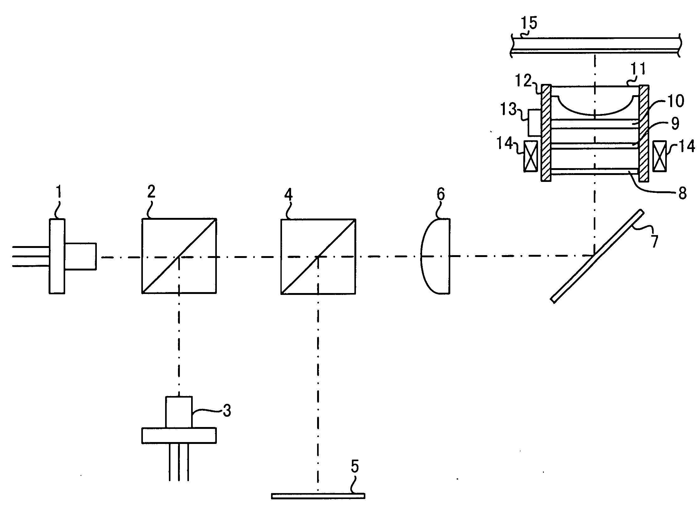
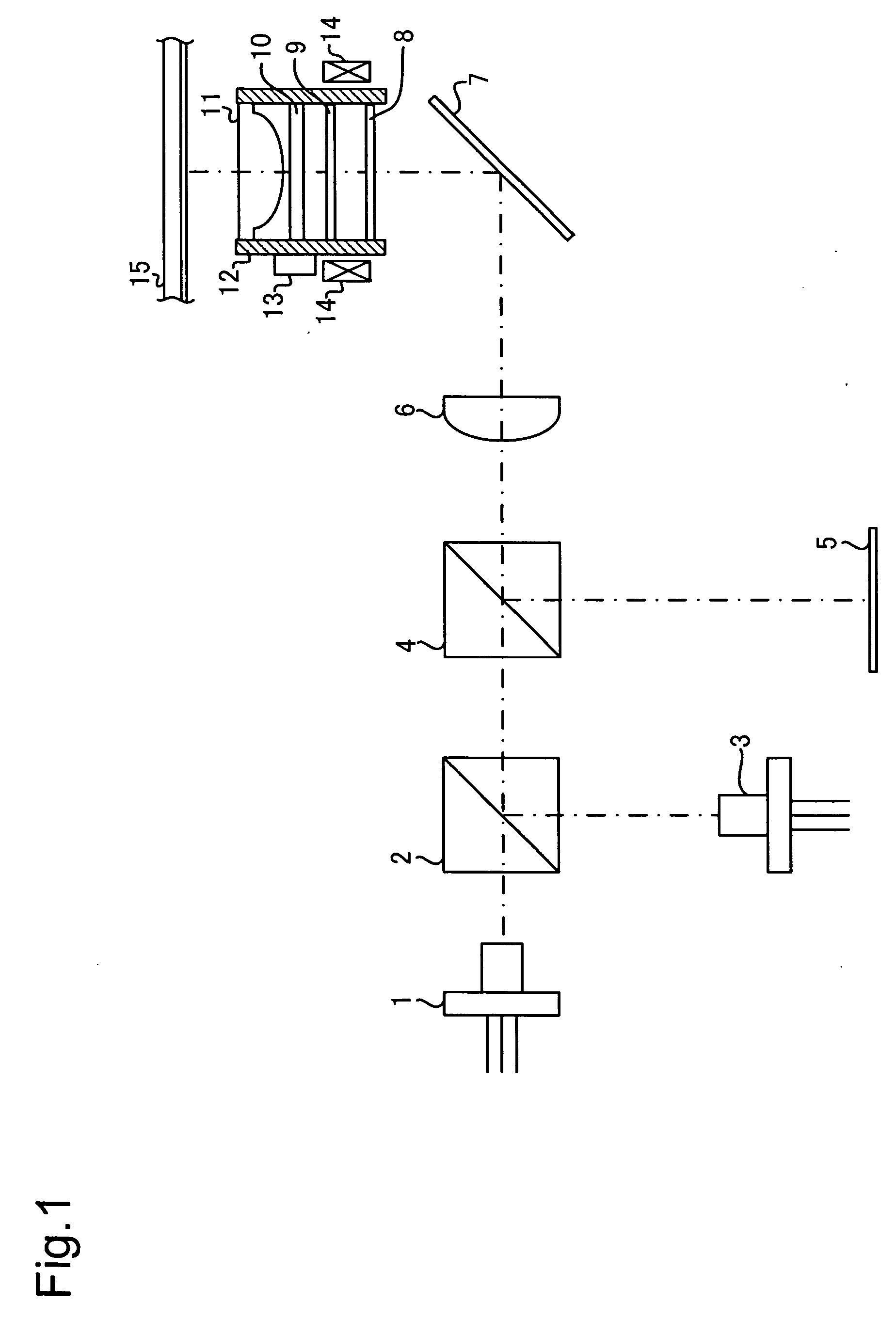
[0022] Now, an embodiment of the present invention will be described with reference to the attached drawings. FIG. 1 shows a general structure of an optical pickup that supports recording and reproducing information on BD (Blu-ray Disc), DVD and CD according to an embodiment of the present invention.

[0023] This optical pickup includes a laser diode 1 for BD, a dichroic prism 2, laser diode 3 for DVD and CD, a polarizing beam splitter 4, a photo detector 5, a collimator lens 6, a mirror 7, a hologram element 8, a wavelength selective aperture 9, a liquid crystal element 10, an objective lens 11 for BD, a lens holder 12, a liquid crystal drive IC 13 and an actuator 14.

[0024] Together with the objective lens 11 for BD, the hologram element 8, the wavelength selective aperture 9, the liquid crystal element 10 and the liquid crystal drive IC 13 are mounted on the lens holder 12. The lens holder 12 is retained by a pickup base (not shown) via a plurality of suspension wires (not shown)....


PUM


Abstract

An optical pickup includes a light source, an objective lens for condensing a light beam emitted from the light source on a disk, a hologram element for splitting the light beam reflected by the disk, a photo detector for receiving the split light beam, a holding element for holding the objective lens and the hologram element, and an actuator for driving the holding element, the objective lens and the hologram element as one unit to shift in a tracking direction.

Description

[0001] This application is based on Japanese Patent Application No. 2005-329702 filed on Nov. 15, 2005, the contents of which are hereby incorporated by reference.BACKGROUND OF THE INVENTION [0002] 1. Field of the Invention [0003] The present invention relates to a structure of an optical pickup for reproducing and recording information on an optical disk. [0004] 2. Description of Related Art [0005] A disk drive for reproducing and recording information on an optical disk such as a CD, a DVD or a Blu-ray Disc (hereinafter referred to as BD) performs a tracking servo that is a control for making a beam spot follow a track on a disk. [0006] An optical pickup that is provided to a conventional disk drive is disclosed in JP-A-2005-158102, for example, which is capable of reproducing and recording information on all types of a high density DVD, a DVD and a CD. In this optical pickup, a spherical aberration of a laser beam emitted from the laser diode LD 1 for high density DVD is correcte...

Claims


Application Information

Patent Timeline
Patent Type & Authority Applications(United States)
IPC IPC(8): G11B7/00
CPCG11B7/0903G11B7/1353G11B7/1369
Inventor TAKAHASHI, KAZUHIROKAMIOKA, YUICHIIKEDA, ATSUSHI
Owner FUNAI ELECTRIC CO LTD
Learn More