Fluid dynamic bearing unit

a technology of fluid dynamic bearing and unit, which is applied in the direction of sliding contact bearing, record information storage, instruments, etc., can solve the problems of insufficient measures alone, inability to quickly manufacture a large quantity of fluid dynamic bearing devices with high performance and high reliability, and the limitations of roller bearings themselves. to be recognized, the assembly accuracy of each element that forms the fluid dynamic bearing unit is improved, and the accuracy of the element assembly is improved

Inactive Publication Date: 2007-05-17
MINEBEA CO LTD
View PDF12 Cites 21 Cited by
  • Summary
  • Abstract
  • Description
  • Claims
  • Application Information

AI Technical Summary

Benefits of technology

[0024] Furthermore, in the above embodiments of the fluid dynamic bearing, a step part is formed in the lower end part of the case element, the end plate element is fit together with said step part, and the lower end part of the case element is made so as to be closed. Exceptional accuracy is obtained due to the fact that grinding of the inner circumferential surface of the case element and the step part can be done at the same time in one setting. The right angle between the upper surface of the end plate and the shaft center of the case element becomes easy to produce, the assembly accuracy of each element that forms the fluid dynamic bearing unit is improved, and high relative rotational accuracy of the shaft element is obtained.

Problems solved by technology

However, these measures alone are not sufficient, and the limitations of roller bearings themselves have come to be recognized.
Thus, it was not easy to quickly manufacture a large quantity of fluid dynamic bearing devices with high performance and high reliability.
However, the structures and dimensions of these modularized components are specified, first and foremost, for adapting to these spindle motors and are not standardized for various equipment and devices to be commonly used.

Method used


Image

  • Fluid dynamic bearing unit
  • Fluid dynamic bearing unit
  • Fluid dynamic bearing unit

Examples


embodiment 1

[0041] Next, embodiment 1 of the invention of this application will be explained.

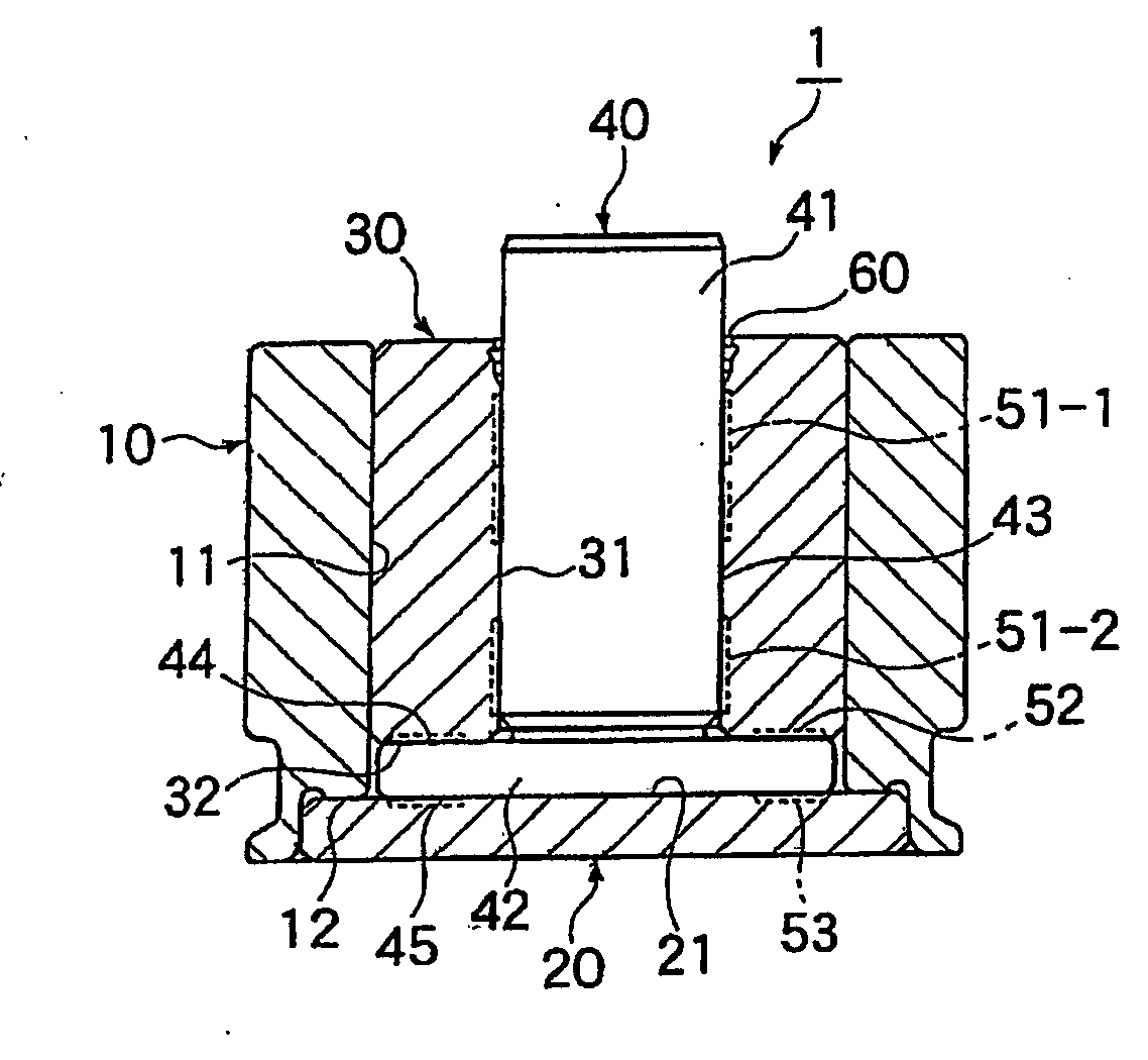
[0042]FIG. 1 is a cross-sectional view of embodiment 1 of a fluid dynamic bearing unit 1. The fluid dynamic bearing unit 1 freely supports relative rotation of a flange-attached shaft element 40 having a flange part 42 on one end (the lower edge in FIG. 1). The flange-attached shaft element 40 has a main part 41 having an outer circumferential surface 43. The flange part 42 has an upper surface 44 and a lower surface 45. The fluid dynamic bearing unit 1 has a tubular case element 10 having a cylindrical shaped inner circumferential surface 11, and a disc shaped end plate element 20 that closes the lower end part of the case element 10. A cylindrical shaped outer ring element 30 fits into the case element 10. The flange part 42 is arranged so as to be sandwiched between a lower end surface 32 of the outer ring element 30 and an upper surface 21 of the end plate element 20. The flange-attached shaft elem...

embodiment 2

[0059] Next, embodiment 2 of the invention of this application will be explained.

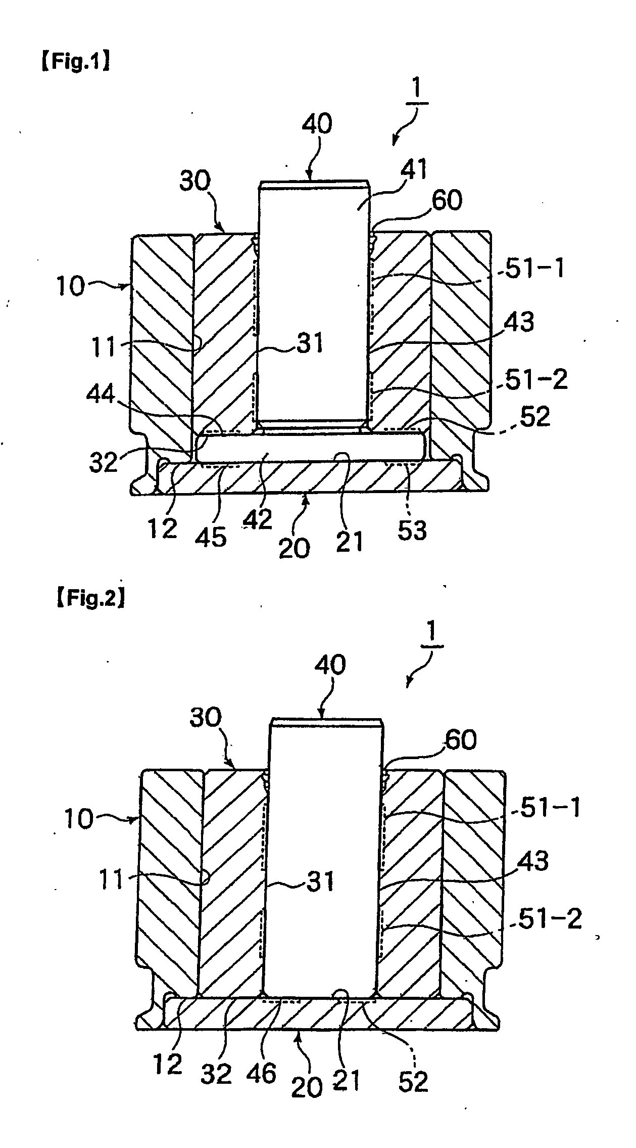
[0060]FIG. 2 is a cross-sectional view of a fluid dynamic bearing unit 1 of embodiment 2. The fluid dynamic bearing unit 1 freely supports relative rotation of a shaft element 40. The shaft element 40 has a main part 41 having an outer circumferential surface 43. The fluid dynamic bearing unit 1 has a tubular case element 10 having a cylindrical shaped inner circumferential surface 11, and a disc shaped end plate element 20 that closes the lower end part of the case element 10. A cylindrical shaped outer ring element 30 fits into the case element 10. The shaft element 40 is inserted into the outer ring element 30.

[0061] First dynamic pressure grooves, for example grooves 51-1, 51-2, are formed on the inner circumferential surface 31 of the outer ring element 30. The first dynamic pressure grooves generate dynamic pressure between the outer circumferential surface 43 and an opposing inner circumferenti...

embodiment 3

[0068] Next, embodiment 3 of the invention of this application will be explained.

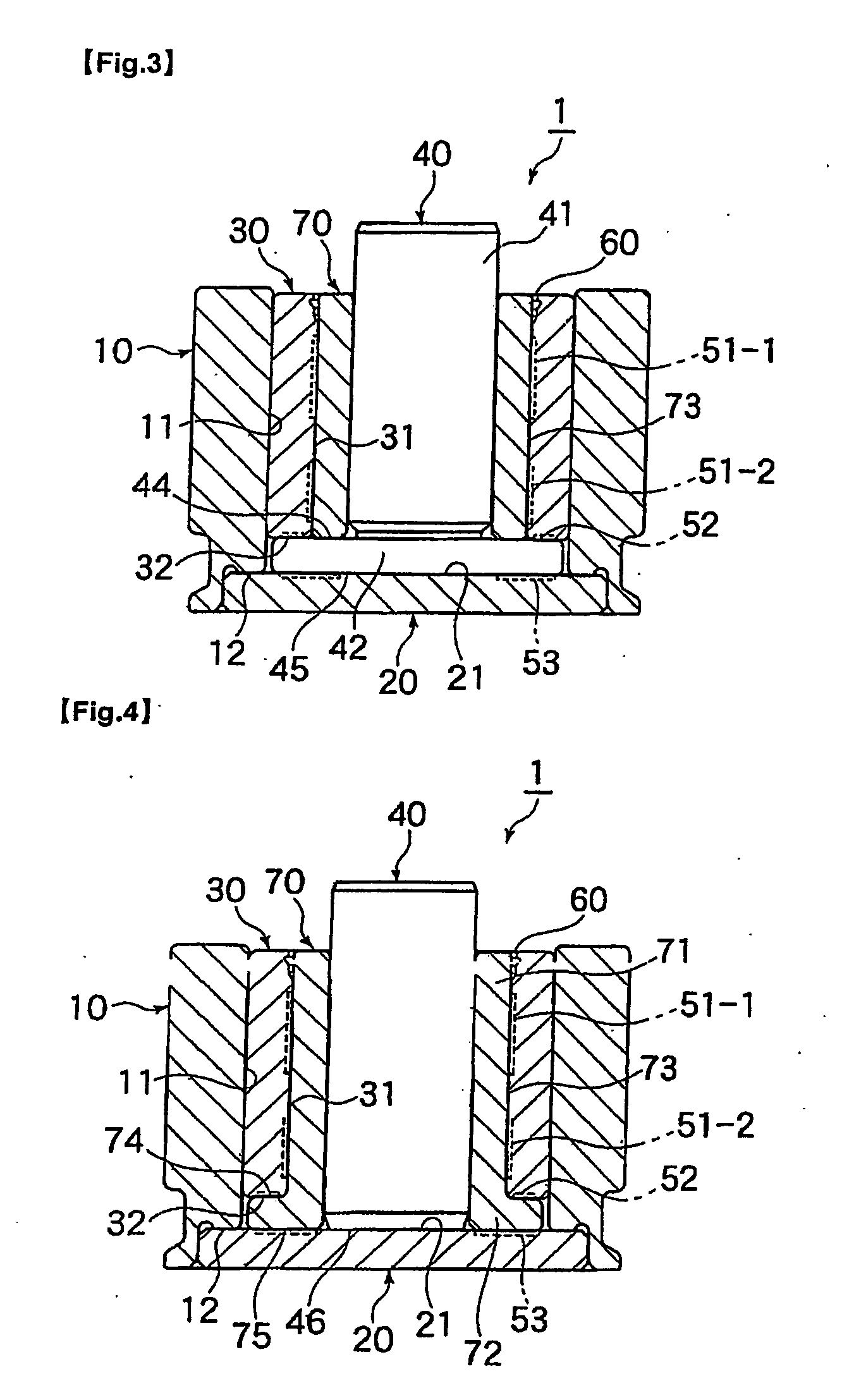
[0069]FIG. 3 is a cross-sectional view of a fluid dynamic bearing unit 1 of embodiment 3. The fluid dynamic bearing unit 1 of embodiment 3 differs from the fluid dynamic bearing unit 1 (FIG. 1) of embodiment 1 in that an outer ring element 30 of the third embodiment is thinner, and an inner ring element 70 is placed in the resulting space between a flange-attached shaft element 40 and the outer ring element 30. The inner ring element 70 rotates relative to the outer ring element 30. The flange-attached shaft element 40 is fit into the inner ring element 70 to form one unit therewith and rotates therewith. The inner ring element 70 and the outer ring element 30 form a bearing in the radial direction. The lower end of the inner ring element 70 contacts an upper surface 44 of a flange part 42 of the flange-attached shaft element 40.

[0070] First dynamic pressure grooves comprised of an upper dynamic press...


PUM

PropertyMeasurementUnit
dynamic pressureaaaaaaaaaa
diameteraaaaaaaaaa
rigidityaaaaaaaaaa

Abstract

A fluid dynamic bearing unit comprised of a plurality of modularized elements that are combined is provided with a case element 10, an end plate element 20, a first outer ring element 30, a second outer ring element 80, a flangeattached shaft element 40, and a spacer element 100. On the inner circumferential surface of the first outer ring element 30 and the inner circumferential surface of the second outer ring element 80, a first dynamic pressure groove 91 and a second dynamic pressure groove 92 are formed to generate dynamic pressure that supports a load in the radial direction. On the upper end surface of the second outer ring element 80 and on the upper surface of an end plate element 20, a third dynamic pressure groove 93 and a fourth dynamic pressure groove 94 are formed to generate dynamic pressure that supports a load in the axial direction. Lubricating oil is filled into the minute gaps corresponding to each of these dynamic pressure grooves. The elements on which the dynamic pressure grooves are formed are made from steel, or stainless steel, which can be hardened. The fluid dynamic bearing units being suitable for use in a hard disk drive such a HDD or DVD.

Description

BACKGROUND OF THE INVENTION [0001] 1. Field Of The Invention [0002] The present invention relates to a fluid dynamic bearing unit for both radial and axial bearing loads. In particular, the present invention relates to a standardized fluid dynamic bearing unit made from modularized components and unitized completed components. The bearing unit being suitable for use in, for example, hard disk drives (HDD's) or Digital Versatile disc drives (DVD's). [0003] 2. Description of Related Art [0004] In recent years, spindle motors have been used as driving devices or components for the rotational parts in office automation equipment such as computers and hard disk drives. These devices, over time, have continuously increased capacity and have been miniaturized. For spindle motors used in these devices, high reliabilities for motor fluctuation accuracy (NRRO (asynchronous fluctuation)), noise, sound duration, rigidity, and the like are strongly desirable. [0005] In the past, for the axle bea...

Claims


Application Information

Patent Timeline
Patent Type & Authority Applications(United States)
IPC IPC(8): F16C32/06F16C17/10F16C33/10G11B19/20H02K5/16
CPCF16C17/026F16C17/107F16C33/107G11B19/2018H02K5/163F16C2370/12
Inventor OBARA, RIKURO
Owner MINEBEA CO LTD
Why Eureka
Try Eureka