Fluid handling apparatus and fluid handling unit for use therein

a technology of fluid handling and handling apparatus, which is applied in the field of fluid handling apparatus and fluid handling unit for use in fluid handling apparatus, can solve the problems of poor reaction efficiency, slow speed of diffusion, and target substance located apart from the bottom and inner walls of the well, so as to improve the efficiency of reaction and the sensitivity of measurement, the effect of shortening the reaction time and the measuring tim

Inactive Publication Date: 2007-05-17
ENPLAS CORP
View PDF9 Cites 6 Cited by
  • Summary
  • Abstract
  • Description
  • Claims
  • Application Information

AI Technical Summary

Benefits of technology

[0017] According to the present invention, it is possible to provide a fluid handling apparatus which is capable of improving the efficiency of reaction and the sensitivity of measurement with a simple structure and of shortening a reaction time and a measuring time, when the apparatus is used as a sample analyzing apparatus for measuring a large number of specimens, and a fluid handling unit for use therein.

Problems solved by technology

Since the molecules in the liquid move while colliding with the surrounding molecules, the speed of diffusion is very slow.
Therefore, in the liquid filled in the well, the target substance located apart from the bottom and inner walls of the well is hardly allowed to react in a practical measuring time.
Therefore, the liquid must be allowed to stand until the reaction occurs after the target substance, antibody and substrate contained in the liquid fed into the well are suspended, circulated and sink to reach the wall surface of the well, so that there is a problem in that the efficiency of reaction is bad.
In addition, in a microplate which is subdivided into a large number of wells, the quantity of liquid fed into each of the wells is limited, so that there is a problem in that the sensitivity of measurement is deteriorated.
However, it is required to provide an external power, such as a pump, in order to control the flowability of liquid, and it is difficult to continuously control the flowability of liquid since the porous material is easily clogged up.
However, it is also required to provide an external power and a complicated device in this method.
However, it is also required to provide power or energy for operating the valve in this method.
However, in the microplate proposed in Japanese Patent Laid-Open No. 9-159673, there is a problem in that it is not possible to improve the efficiency of reaction although it is possible to improve the sensitivity of measurement.
In addition, the microchip proposed in Japanese Patent Laid-Open No. 2001-4628 is not suitable for the measurement of a large number of specimens although it is possible to improve the efficiency of reaction since it is a microchip having a microchannel structure, not a microplate typically used in ELISA or the like.
Moreover, in the microplate proposed in Japanese Patent Laid-Open No. 9-101302, it is not possible to sufficiently improve the efficiency of reaction and the sensitivity of measurement, although it is possible to increase the surface area of the reaction surface to some extent to improve the efficiency of reaction and the sensitivity of measurement.

Method used


Image

  • Fluid handling apparatus and fluid handling unit for use therein
  • Fluid handling apparatus and fluid handling unit for use therein
  • Fluid handling apparatus and fluid handling unit for use therein

Examples


Embodiment Construction

[0030] Referring now to the accompanying drawings, the preferred embodiments of a fluid handling apparatus and a fluid handling unit for use therein according to the present invention will be described below in detail.

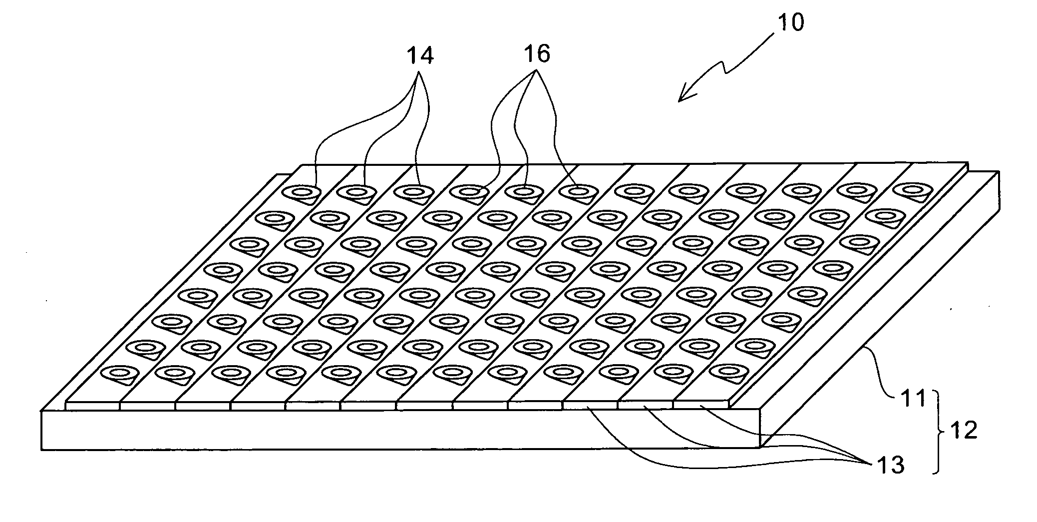
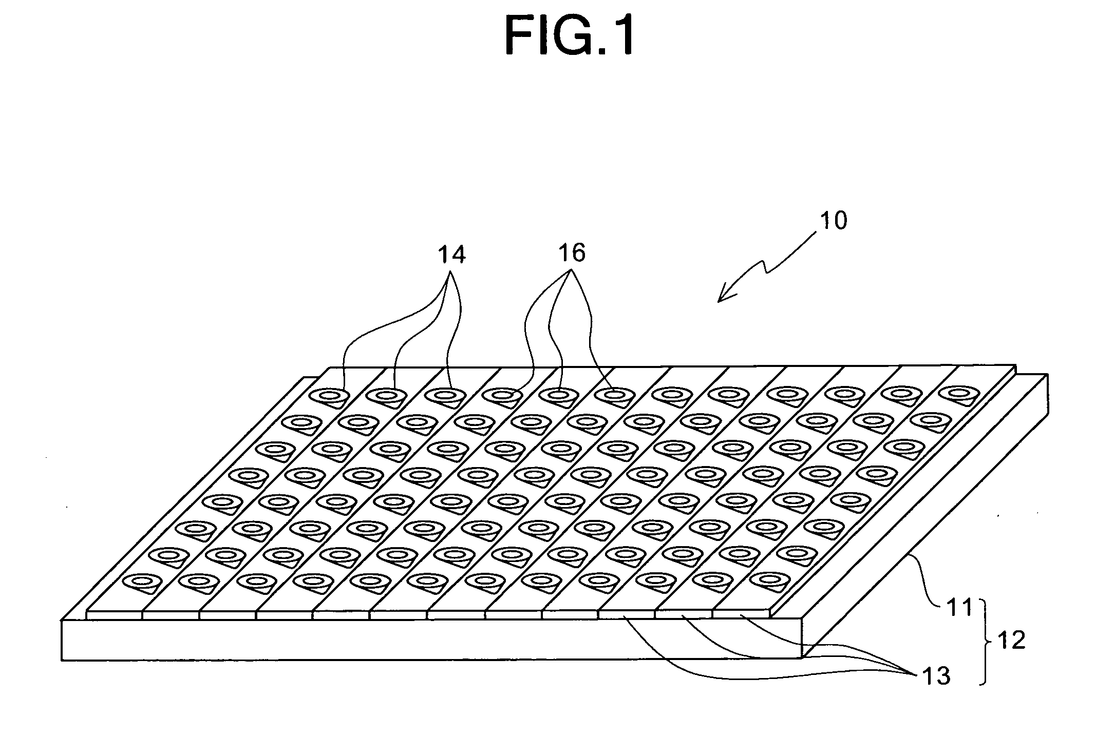
[0031]FIGS. 1 through 7 show the preferred embodiment of a fluid handling apparatus according to the present invention. For example, the fluid handling apparatus 10 in this preferred embodiment can be used as an apparatus for analyzing a sample containing a biosubstance, such as a protein, which is representative of functional substances. In general, the fluid handling apparatus 10 can be used as a sample analyzing apparatus called a microwell plate for carrying out the measurement of a large number of specimens. As shown in FIG. 1, the fluid handling apparatus 10 comprises: an apparatus body 12; and a plurality of fluid handling subassemblies 16 (96 (=8×12) fluid handling subassemblies in this preferred embodiment) mounted on the apparatus body 12.

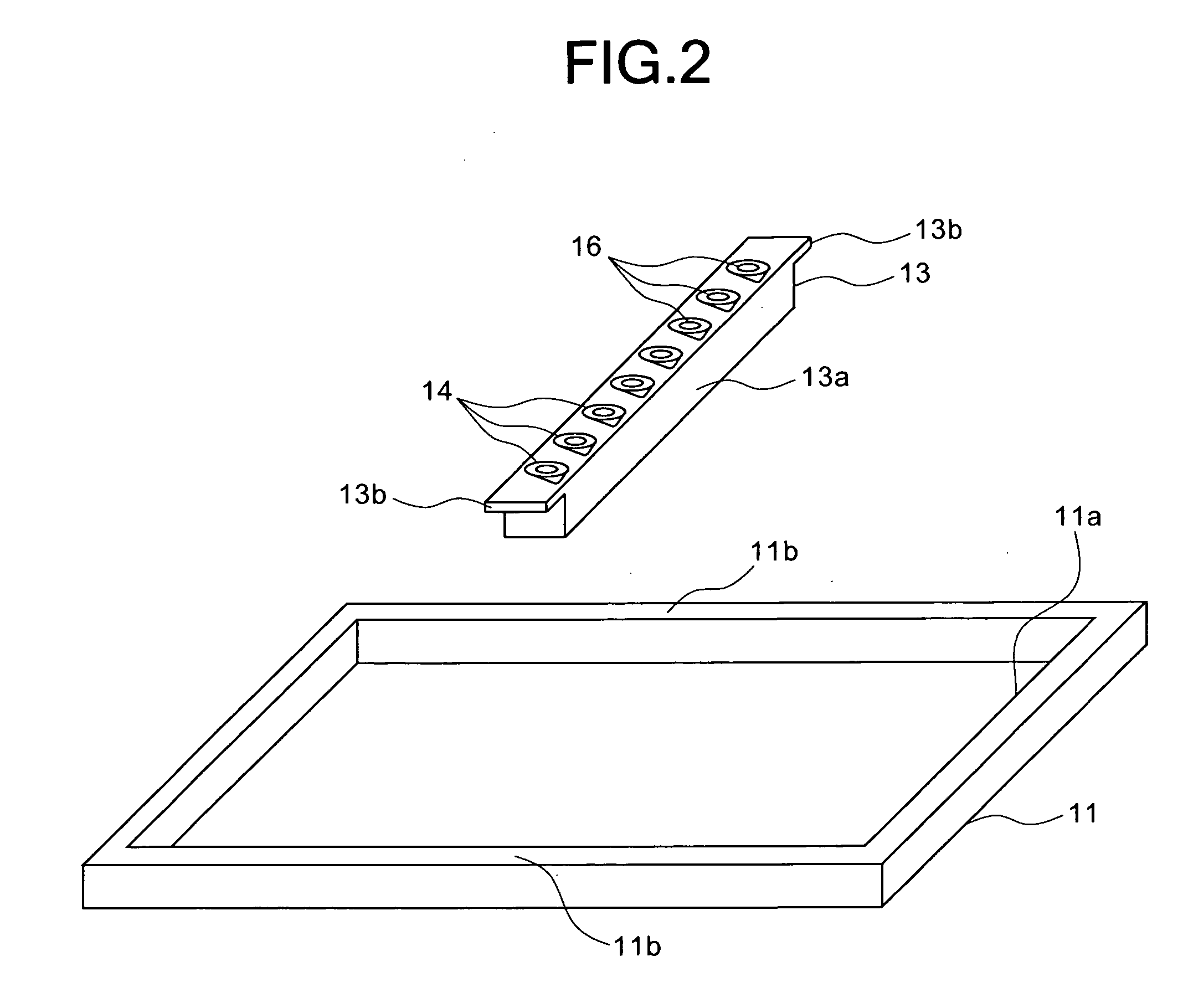
[0032] As shown in...


PUM

PropertyMeasurementUnit
lengthaaaaaaaaaa
diameteraaaaaaaaaa
surface-areaaaaaaaaaaa

Abstract

A fluid handling apparatus 10 has a plurality of fluid handling subassemblies 16, each of which is mounted in a corresponding one of mounting recessed portions 14 of a plate body 12. Each of the fluid handling subassemblies 16 includes: an injecting section 26 for injecting a fluid; a fluidized section 28 for receiving the fluid from the injecting section 26 to allow the fluid to continuously flow downwards; a fluid housing chamber 30 for receiving the fluid from the fluidized section 28; a wall portion 20 formed so as to extend in substantially vertical directions between the fluid housing chamber 30 and the fluidized section 28; an opening 20a for allowing the fluid in the fluidized section 28 to enter the fluid housing chamber 30; and a surface-area increasing means (22, 32, 34) for increasing the area of a contact surface with the fluid in the fluidized section 28.

Description

BACKGROUND OF THE INVENTION [0001] 1. Field of the Invention [0002] The present invention generally relates to a fluid handling apparatus and a fluid handling unit for use therein. More specifically, the invention relates to a fluid handling apparatus capable of being used as a sample analyzing apparatus for analyzing samples, such as biosubstances representative of functional substances, and a fluid handling unit for use therein. [0003] 2. Description of the Prior Art [0004] As conventional methods for specifically detecting biosubstances, such as proteins, there are known various methods for causing an antigen-antibody reaction using an antibody to a specific biosubstance, to carry out the visual recognition or spectroscopic measurement of a reactant thus obtained, to detect the biosubstance. [0005] As methods for quantifying a reactant obtained by an antigen-antibody reaction of a biosubstance, such as a protein, there are widely adopted some methods, such as ELISA (Enzyme-Linked...

Claims


Application Information

Patent Timeline
Patent Type & Authority Applications(United States)
IPC IPC(8): C12M1/34
CPCB01L3/5025B01L3/50855B01L2300/0618B01L2300/0627B01L2300/0681B01L2300/0829
Inventor OHSE, TAKUHITOKAWAHARA, NORIYUKINATSUHARA, MASANOBU
Owner ENPLAS CORP
Why Eureka
Try Eureka