Eureka AIR delivers breakthrough ideas for toughest innovation challenges, trusted by R&D personnel around the world.

Hand-held power tool with foamed cabling

a power tool and foam technology, applied in the field can solve the problems of strand jamming or friction of strands, failure of hand-held power tools, and strand movement relative to each other, and achieve the effects of preventing strand damage or electrical connection damage, convenient mounting, and improved access

Inactive Publication Date: 2007-05-24
HILTI AG
View PDF24 Cites 8 Cited by
  • Summary
  • Abstract
  • Description
  • Claims
  • Application Information

AI Technical Summary

Benefits of technology

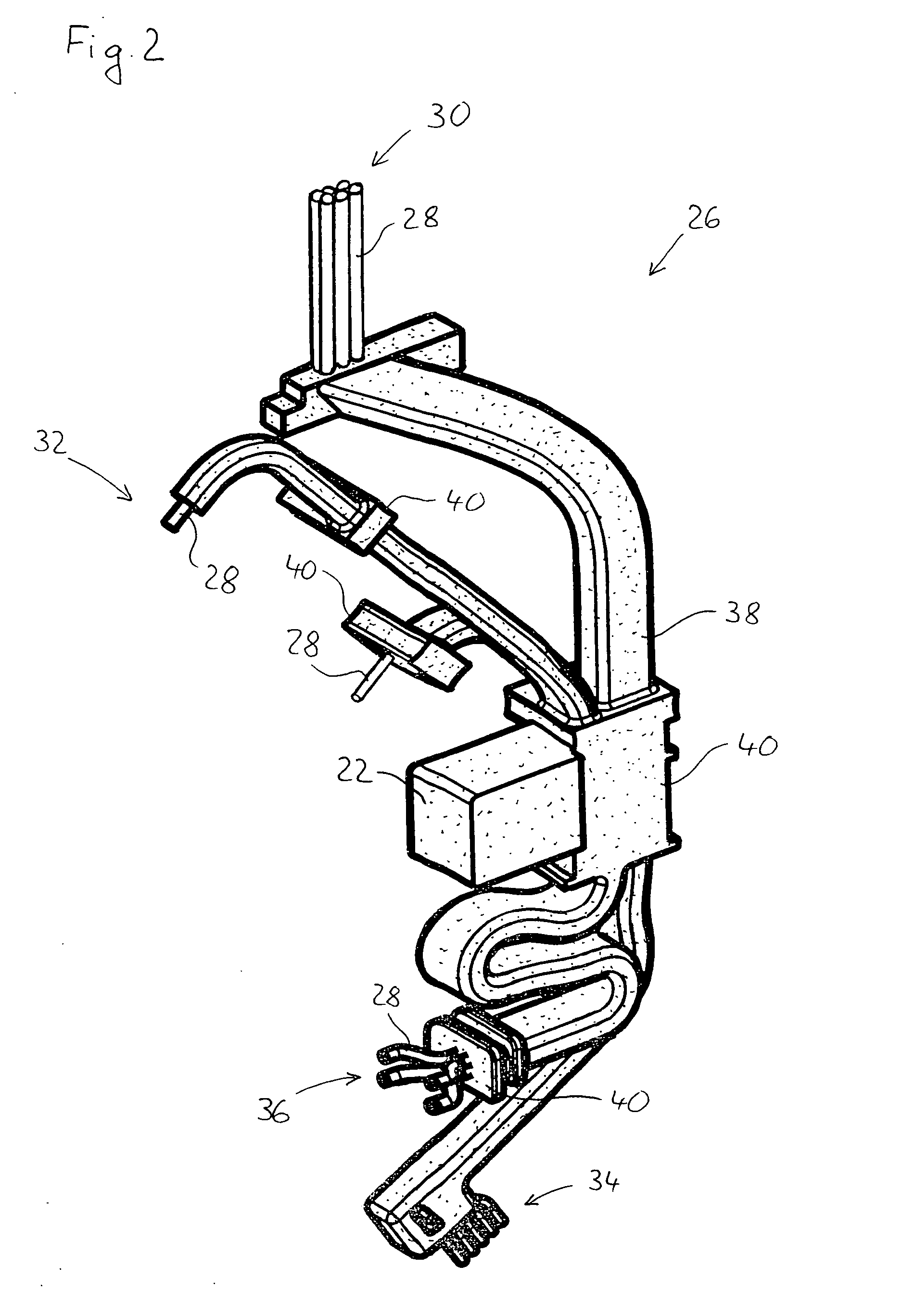
[0008] These and other objects of the present invention, which will become apparent hereinafter, are achieved by providing a foamed protective sheathing for the cabling. With such a protective sheathing from a foamed material, the damage of strands from friction can be effectively prevented. In addition, the protective sheathing can be formed sufficiently rigid to prevent jamming of the cabling between movable relative to each other parts during an operation.
[0009] According to a particular advantageous embodiment of the invention, the cabling includes, at least sectionwise, two parallel strands which are so embedded in the protective sheathing that they are arranged as close to each other as possible. This prevents the regions of the strands from rubbing against each other and from a resulting therefrom damage. In addition, the use of the protective sheathing permits to simultaneously handle two or more strands, which noticeably facilitate mounting of the cabling in a hand-held power tool.
[0011] Advantageously, the protective sheathing has at least one stretchable curvature. “Stretchable” should be understood that the protective sheathing is not secured to any element of a hand-held power tool at least along a section of the curvature. With a such stretchable curvature, there is provided, in a mounted condition of the cabling, a longitudinal play of the protective sheathing or of the strands. Thereby, the changes of the distance between the connected regions or between the electrical or electronic elements, which occur during an operation as a result of the relative movement between the handle and main housings, can be better compensated. In this way, the danger of the strands or their electrical connections being damaged is prevented. In addition, the longitudinal play permits to displace the connection region or element relative to another connection region or element, e.g., for repair or mounting, in order to insure a better access.
[0012] Advantageously, the protective sheathing envelopes at least one electrical or electronic component of the power tool which is connected with the cabling. Thereby, in addition to the cabling, electrical and / or electronic components such as, e.g., condensers, are also protected against damage that might be caused by vibrations or blows generated during an operation. Moreover, with a certain rigidity or stiffness of the protective sheathing, a subassembly is produced that be mounted particularly easy. It can be produced separately from the hand-held power tool and be first assembled therewith during the final assembly.
[0013] Advantageously, the sheathing forms a terminal member that cooperates with a support formed integrally with the handle housing. In this way, the protective sheathing, together with the cabling, and if necessary with other technical and / or electronic components, can be rapidly and easily mounted in the power tool. The protective sheathing can be exactly positioned, so that an adequate freedom of movement for compensating the occurring relative movements between the handle and main housings is insured, without any damage caused by friction.
[0014] According to a further advantageous embodiment of the present invention, the protective sheathing is formed of a duroplastic polyurethane foam, which insures a more easy manufacturing and, at the same time, a high abrasive resistance and a satisfactory flexibility.

Problems solved by technology

The drawback of the known hand-held power tool consists in that the strands are loosely arranged in the connection region and abut each other and the housing parts.
The vibrations generated during operation and the resulting relative movement between the handle and main housings cause movement of strands relative to each other and relative to the housing.
This relative movement can easily lead to jamming of a strand or to friction of strands with each other and / or with the housing.
This can result, in particular with the presence of drillings within the interior of the housing, to damage of the cabling which, in turn, can lead to failure of the hand-held power tool.

Method used


Image

  • Hand-held power tool with foamed cabling
  • Hand-held power tool with foamed cabling
  • Hand-held power tool with foamed cabling

Examples


Embodiment Construction

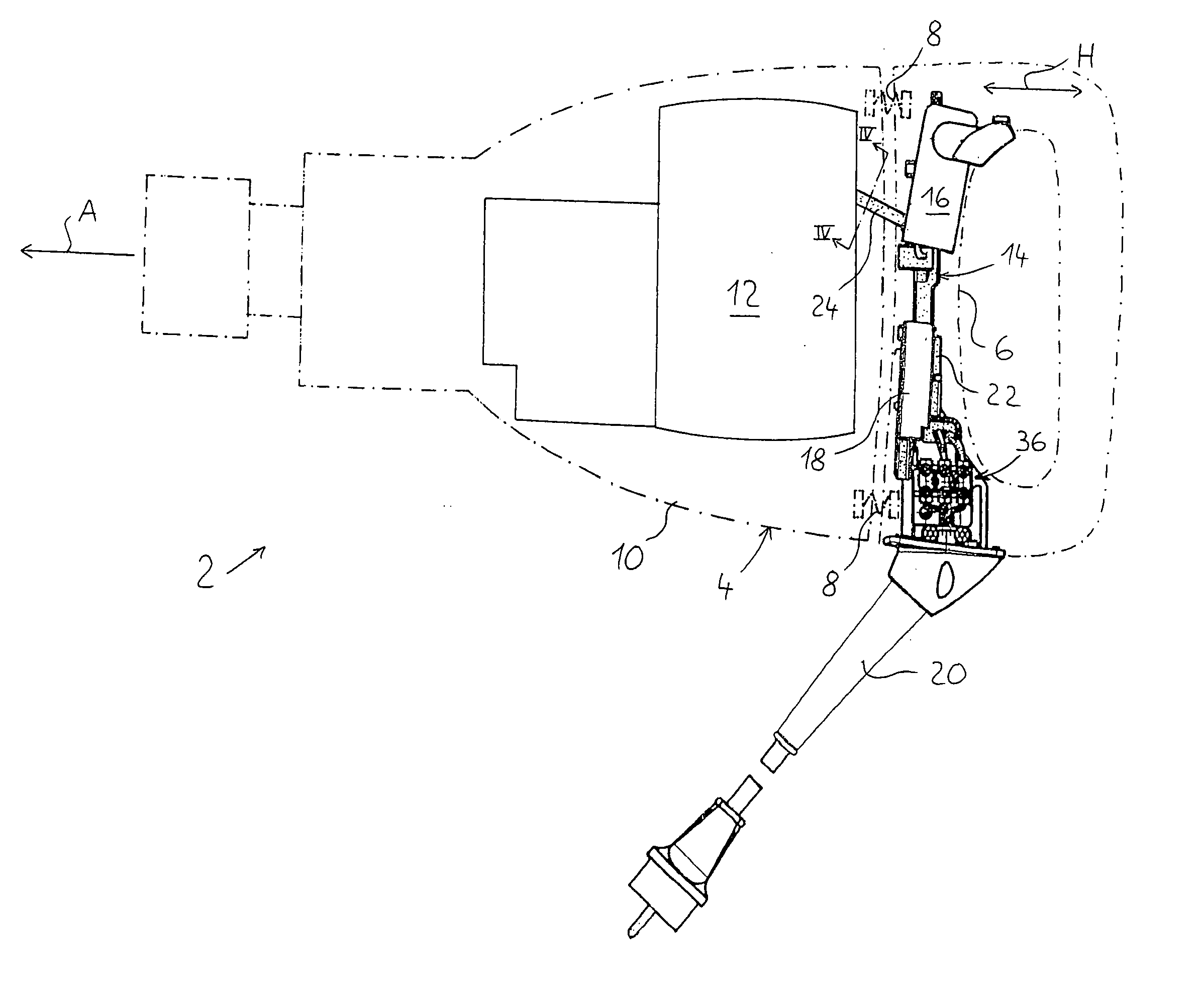
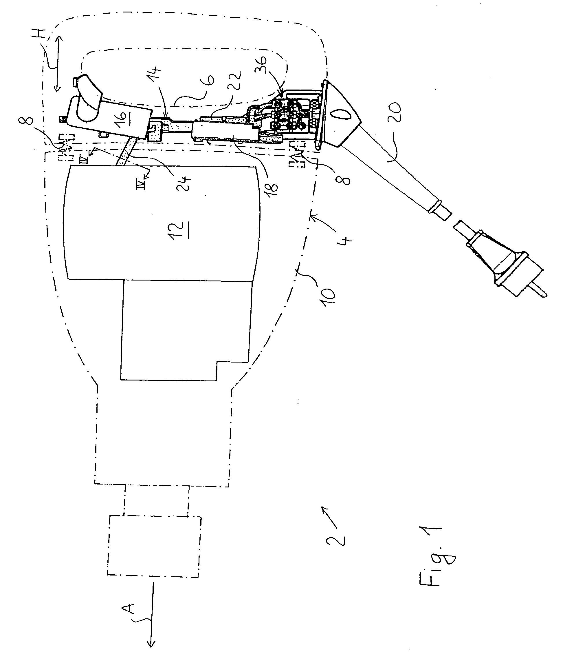
[0022] An electrical hand-held power tool 2 according to the present invention, which is shown in FIG. 1, is formed as a chisel power tool and has a two-housing 4. The housing 4 has a handle housing 6 that is held on a main housing 10 by vibration reducing means 8 which is schematically shown by a spring. The vibration reducing means 8 can be formed by resiliently elastic means, damping means, or a combination of both. In each case, the handle housing 6 is displaceably held relative to the main housing 10, displacing along a first spatial direction H parallel to an operational direction A of the hand-held power tool 2. In addition, the handle housing 6 can be displaced relative to the main housing 10, within narrow limits, in one or both spatial directions transverse to the first spatial direction H.

[0023] In the main housing 10, there is located a drive motor 12 of the hand-held power tool 2. The drive motor 12 is electrically connected by cabling, which is generally designated wi...


PUM


Abstract

A hand-held power tool includes a main housing (10) in which a drive motor (12) located, a handle housing (6) connected with the main housing (10) with a possibility of a limited displacement relative thereto in at least one spatial direction (H), a motor switch (16) provided on the handle housing (6), and a cabling (14) for electrically connecting the motor switch with the drive motor (12) and surrounded by protective sheathing (38).

Description

BACKGROUND OF THE INVENTION [0001] 1. Field of the Invention [0002] The present invention relates to a hand-held power tool that generates vibration during operation such as, e.g., an electrical hammer drill, a chisel or percussion drilling tool, a motor driven saw, in particular, such as a compass or saber saw, or a cutting or grinding tool, in particular an angle grinder. The hand-held power tool includes a main housing, a drive motor located in the main housing, and a handle housing. The handle housing is connected with the main housing with a possibility of a limited displacement relative thereto in at least one spatial direction. A motor switch is provided on the handle housing. The motor switch is actuated by a push-button and is electrically connected with the drive motor by cabling. [0003] 2. Description of the Prior Art [0004] As a result of the relative movement of the handle housing relative to the main housing, the hand-held power tools of this type are equipped with vib...

Claims


Application Information

Patent Timeline
Patent Type & Authority Applications(United States)
IPC IPC(8): E21B17/22
CPCB25D17/043B25D2250/041B25F5/006
Inventor EGE, MANFREDPASZEHR, KAYLUEBKERT, ERNST-RUDOLF
Owner HILTI AG
Why Eureka
Eureka Blog
Learn More