Directed energy off-body heating for supersonic vehicle shockwave and sonic boom control

a supersonic vehicle and energy off-body heating technology, applied in the direction of airflow influencers, fuselages, transportation and packaging, etc., can solve the problems of financial impracticality in creating the next generation of supersonic transports, noise conditions on the ground, and the inability to create large commercial supersonic transports, so as to reduce the number of supersonic aircraft, reduce the wave drag associated with supersonic vehicles, and suppress noise and sonic booms

Inactive Publication Date: 2007-05-24
THE BOEING CO
View PDF5 Cites 11 Cited by
  • Summary
  • Abstract
  • Description
  • Claims
  • Application Information

AI Technical Summary

Benefits of technology

[0004] It is in view of the above problems that the present invention was developed. The invention provides methods and apparatus for suppressing noise and sonic booms from supersonic vehicles. Accordingly, the present invention enables the development of small or large, commercially viable, supersonic transport aircraft. Even the focused sonic booms produced by lower Mach number supersonic aircraft during maneuvering can be suppressed i

Problems solved by technology

These shockwaves and sonic booms create noise conditions on the ground that are unacceptable to the general public and prohibited by FAA regulations.
As a result, it has proven to be impractical to create large commercial supersonic transports, such as that envisioned by the NASA High Speed Civil Transport (HSCT) program that can operate over inhabited areas.
For instance, the European Concorde, which operated at supersonic speeds, was limited to only over water operation, and was restricted to only selected airports while it was in service because of the noise associated with its flight.
Such limitations make it financially

Method used


Image

  • Directed energy off-body heating for supersonic vehicle shockwave and sonic boom control
  • Directed energy off-body heating for supersonic vehicle shockwave and sonic boom control
  • Directed energy off-body heating for supersonic vehicle shockwave and sonic boom control

Examples


Embodiment Construction

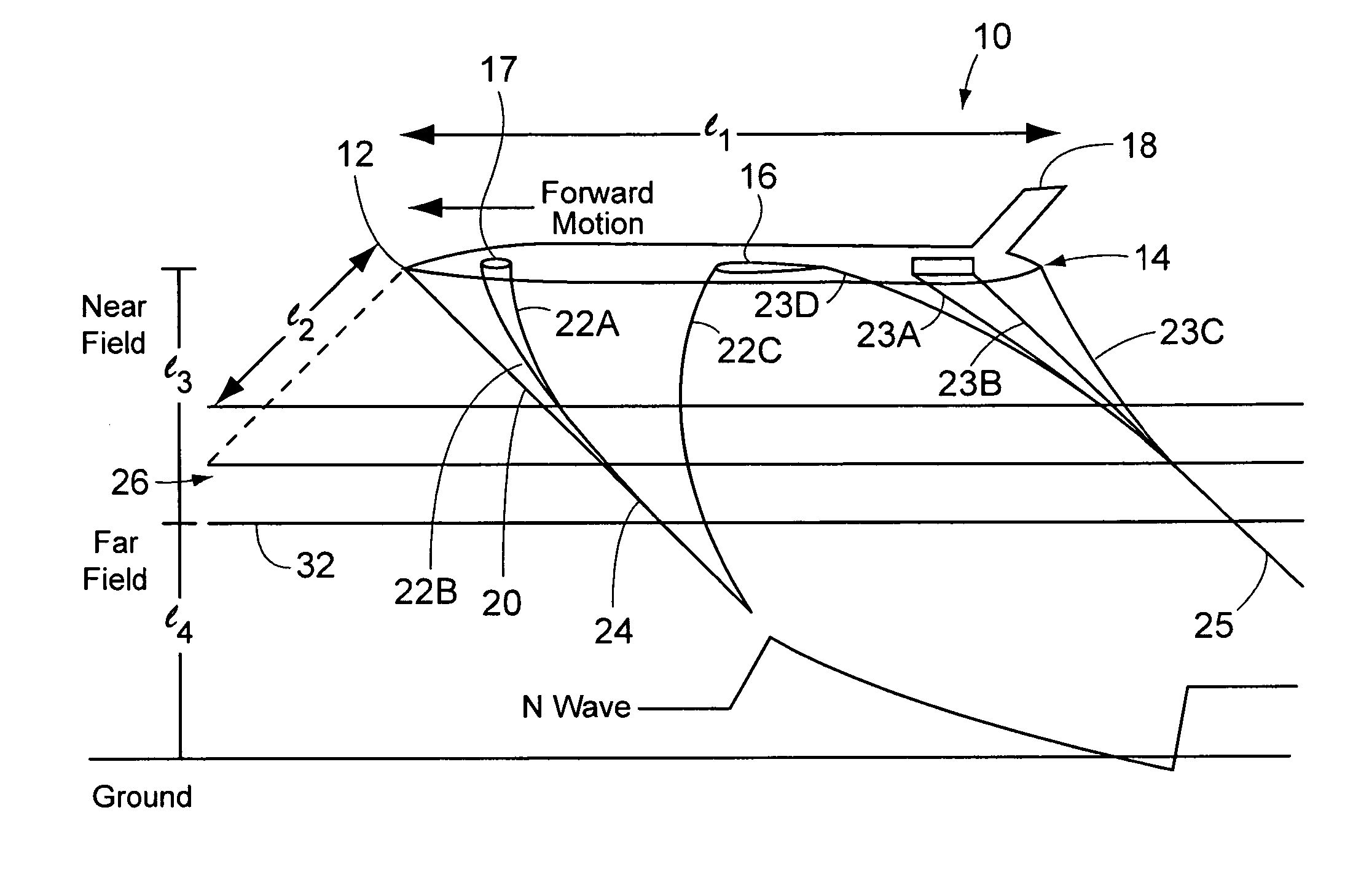
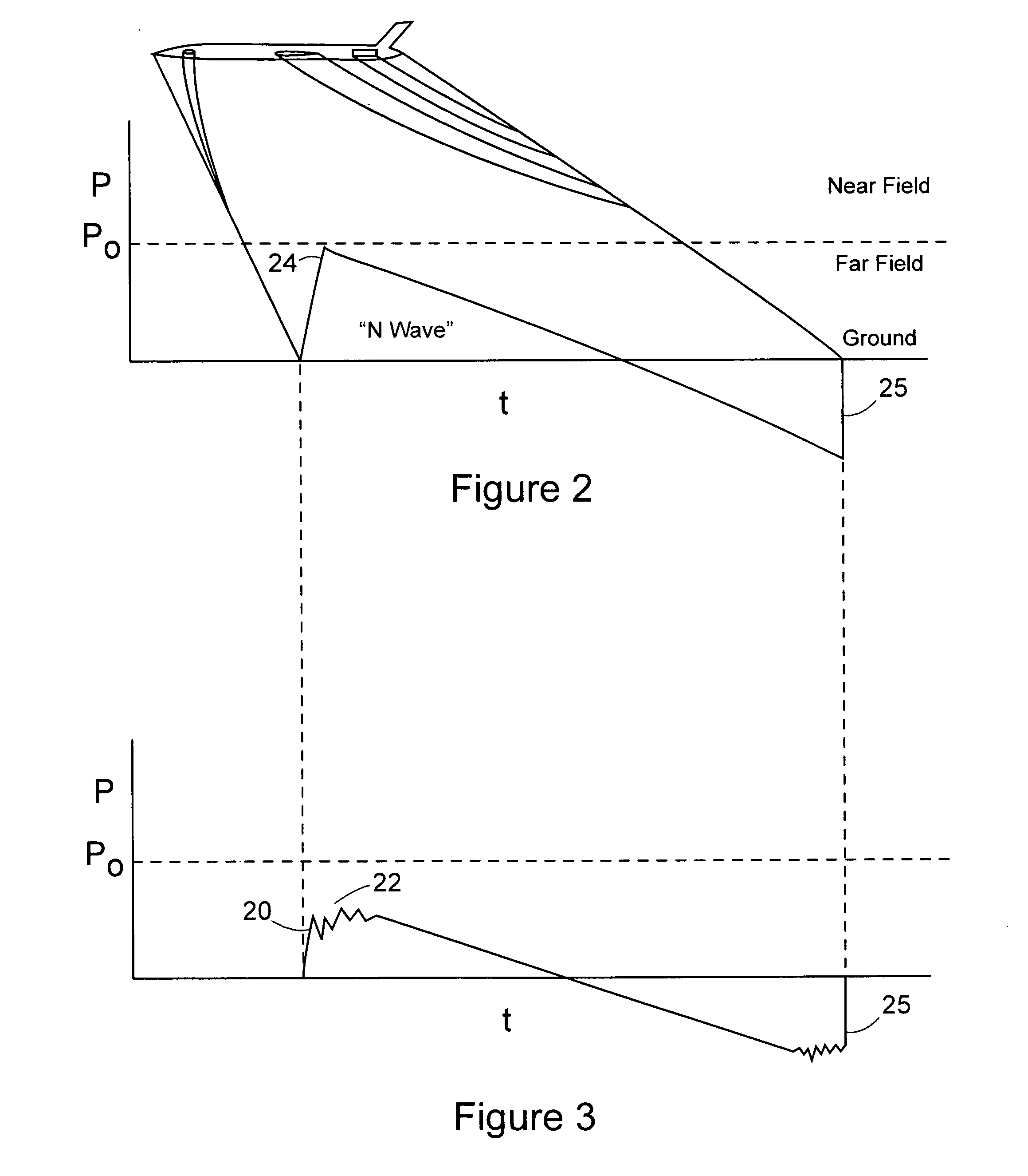
[0020] Referring to the accompanying drawings in which like reference numbers indicate like elements, FIG. 1 illustrates a supersonic vehicle traveling through an atmosphere. The vehicle 10 includes an airframe composed of various major sub-assemblies such as a nose 12, a tail cone 14, wings 16, a canard wing 17, a tail 18, and an engine 19. Each portion of the vehicle can create shock waves as the vehicle 10 moves through the atmosphere at supersonic speeds of which several exemplary shock waves are illustrated. The shock wave 20 is caused by the nose 12 pushing air out of its way. Similarly, shock waves 22A and 22B are shown arising from the canard wing 17 aft of the nose 12 of the vehicle 10. In the flow field far below the vehicle (greater than about 10 aircraft lengths from the aircraft 10 and hereinafter the “far field”) the various shockwaves 20, 22A, 22B, and 22C generally propagate from the vehicle 10 at or near their original mach angles and therefore remain spaced apart f...


PUM


Abstract

Methods and apparatus for suppressing noise. The present invention provides a method that includes directing a laser at a first volume of gas and directing microwave radiation to a second volume. The method includes selecting the location of the second volume so that it is overrun by a shockwave system of a supersonic vehicle. Preferably, the directing of the radiation is from a vehicle that flies at high altitude and is of practical length (e.g., 100-400 feet or more). The radiation may be pulsed and steered. The present invention also provides a system including a laser and microwave antenna for controlling the noise of a supersonic vehicle. The laser is directed at a first volume while the antenna is pointed at a second volume that envelops the first volume. The location of the second volume is such that it will be overrun by the shockwave system of the vehicle.

Description

FIELD OF THE INVENTION [0001] This invention relates generally to sonic boom control and, more particularly, to sonic boom control using energy directed to the far field of the vehicle. BACKGROUND OF THE INVENTION [0002] The motion of a vehicle through the atmosphere at high supersonic speeds (particularly at Mach numbers greater than 1.4) produces shockwaves from the vehicle fore-body, lifting surfaces, propulsion systems, tail structures and other elements. These shockwaves coalesce far below the vehicle and before they reach the ground and form overpressure regions associated with the phenomenon referred to as a sonic boom. These shockwaves and sonic booms create noise conditions on the ground that are unacceptable to the general public and prohibited by FAA regulations. As a result, it has proven to be impractical to create large commercial supersonic transports, such as that envisioned by the NASA High Speed Civil Transport (HSCT) program that can operate over inhabited areas. ...

Claims


Application Information

Patent Timeline
IPC IPC(8): B64C30/00B64D47/00
CPCB64C2220/00B64C30/00
Inventor SMERECZNIAK, PHILIP
Owner THE BOEING CO
Why Eureka
Try Eureka