Nano tip and fabrication method of the same

Active Publication Date: 2007-05-24
KOREA INST OF MASCH & MATERIALS
View PDF4 Cites 15 Cited by
  • Summary
  • Abstract
  • Description
  • Claims
  • Application Information

AI Technical Summary

Benefits of technology

[0032] As explained hereinabove, according to the fabrication method of the nano tip of the present invention, a nano tip having improved stiffness and perpendicularity is fabricated by adjusting the length, the diameter, and the shape of the end of the carbon nanotube tip attached with carbon nanotubes by means of the energy beam so that t

Problems solved by technology

However, it is very difficult to fabricate a nanoscale probe with these carbon nanotubes attached.
In particular, previously reported methods take a long time for production in even a small quantity or have the disadvantage that uniform performance is not obtained in mass production.
Also, it is nearly impossible to obtain the required length and diameter and to control the shape of the end of the tip.
Therefore, when measuring samples, each tip may show the different result so that the

Method used


Image

  • Nano tip and fabrication method of the same
  • Nano tip and fabrication method of the same
  • Nano tip and fabrication method of the same

Examples


first embodiment

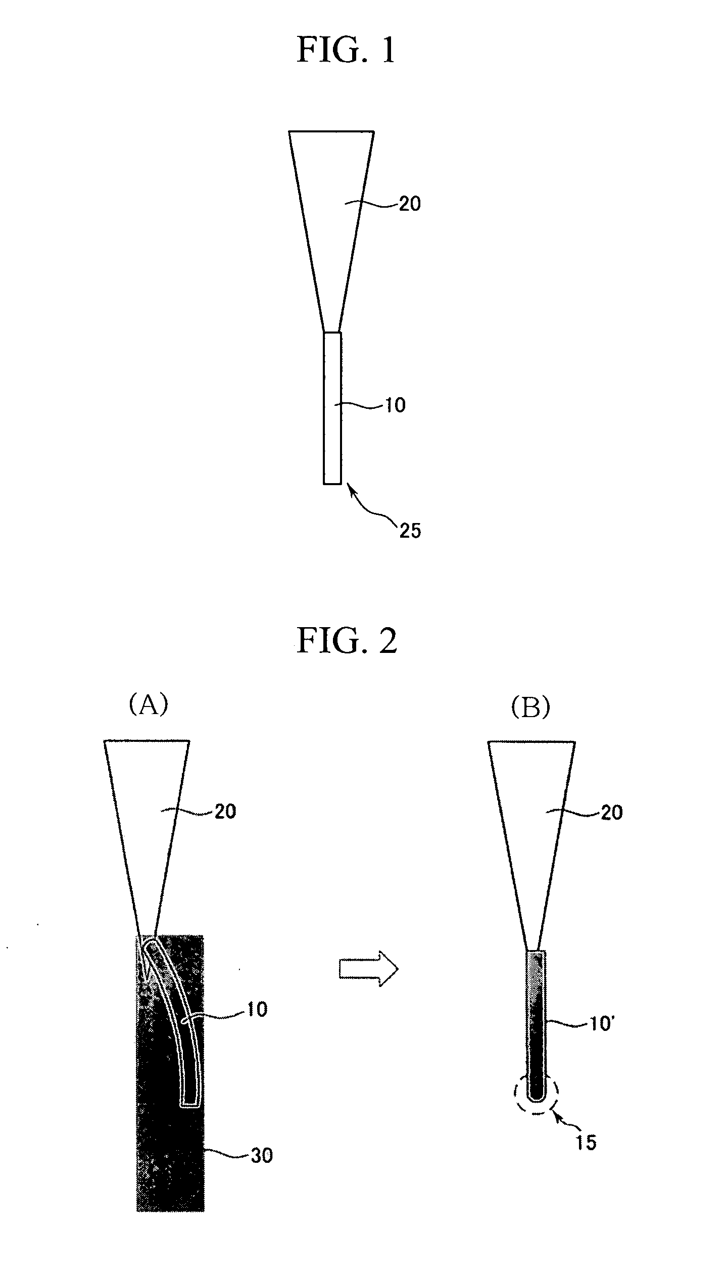
[0054] FIGS. 2(A) and 2(B) are schematic diagrams showing the process for improving perpendicularity of the nano tip by the energy beam in the fabrication method of the nano tip according to the present invention.

[0055] In the case that the carbon nanotube 10 that is bonded to the supporting holder 20 is curved or has a rough surface, the carbon nanotube 10 changes in shape over time while the energy beam 30 is applied. That is, when the energy beam 30 is applied for a predetermined duration, the carbon nanotube 10 is gradually straightened and may become a smooth surfaced carbon nanotube 10′.

[0056] In particular, it has been reported that the carbon nanotube changes from an sp2 to an sp3 structure due to ion bombardment when a focused ion beam (FIB) is scanned to the carbon nanotube. The previous study shows that a hollow carbon nanotube becomes a solid carbon nanotube of which the interior is completely filled in such a changing process.

[0057] Therefore, the carbon nanotube on t...

second embodiment

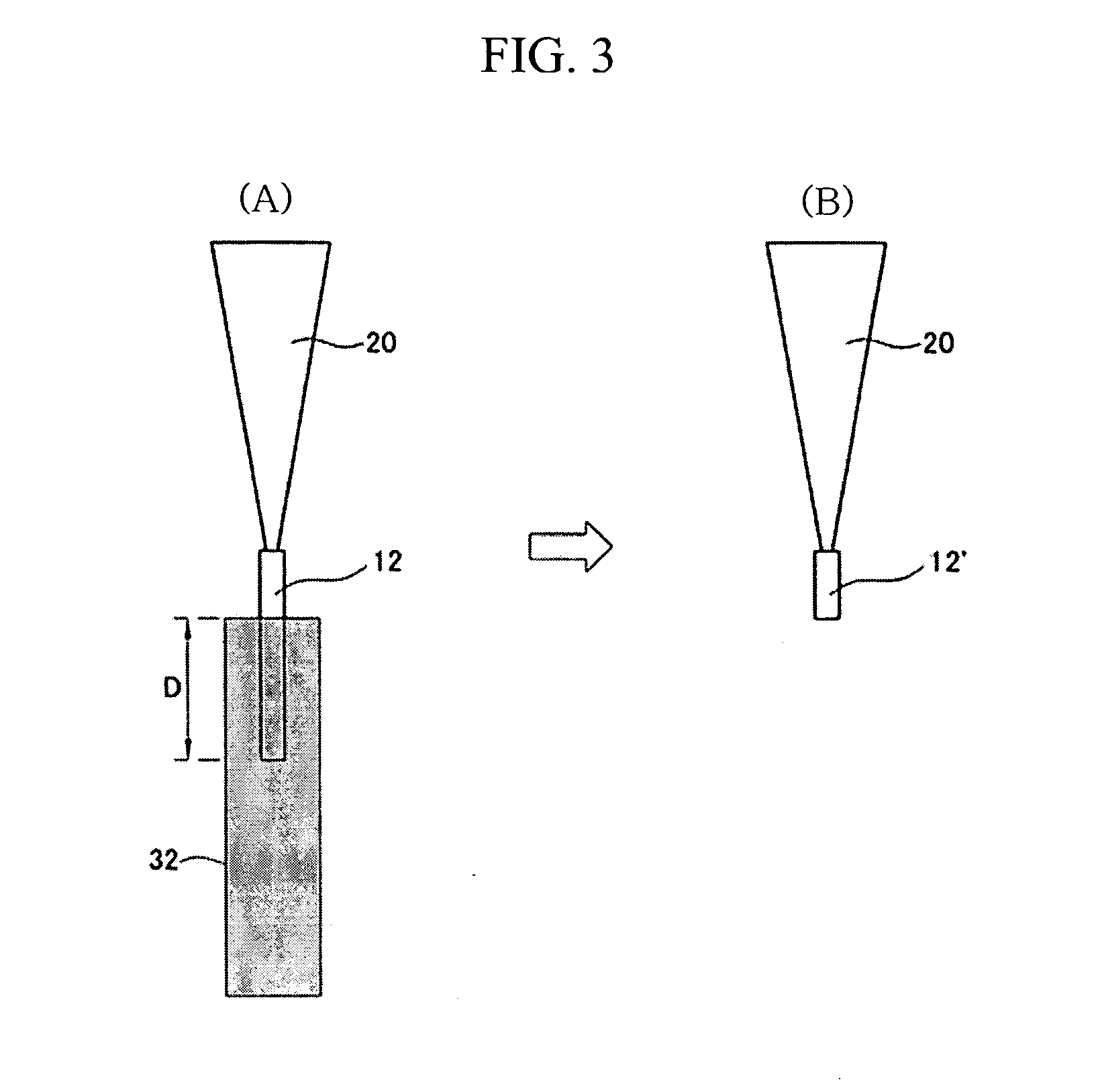
[0059] FIGS. 3(A) and 3(B) are schematic diagrams showing the process for cutting the nano tip by the energy beam in the fabrication method of the nano tip according to the present invention. In the present embodiment, the bonded carbon nanotube or the nano rod that is changed to be vertical by exposure to the energy beam may be cut to a required length.

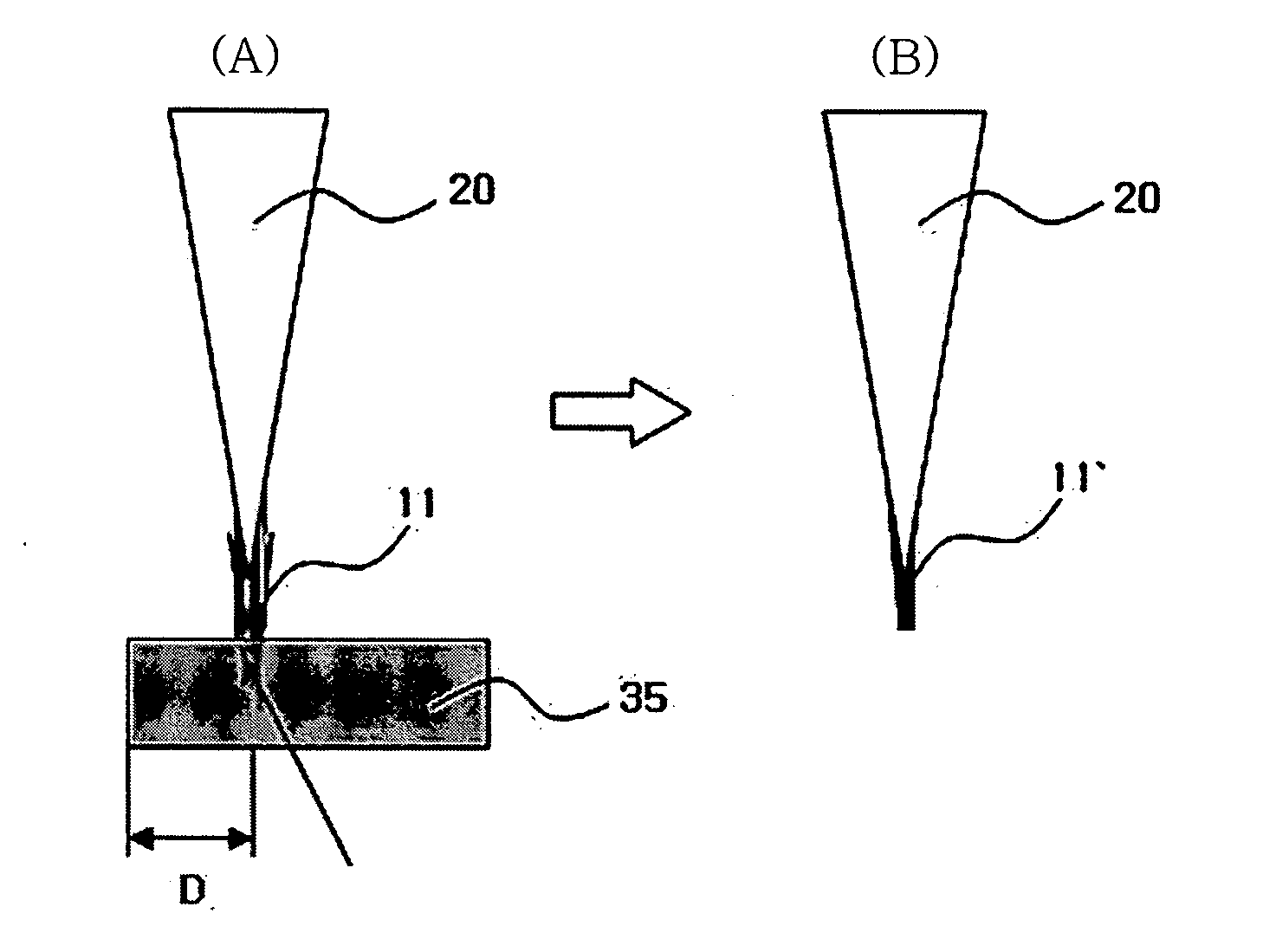
[0060] Generally, the high-powered ion beam has the feature of cutting the surface where the beam is scanned. By using the feature, the carbon nanotube 12 (or nano rod) that is aligned along the protruding direction of the end of the supporting holder 20 may be cut to the short carbon nanotube 12′ (or nano rod) when the ion beam is scanned in the lengthwise direction of the carbon nanotube 12 (or nano rod) with the focus set at a proper location within the carbon nanotube 12 (or nano rod). The length to be cut off is proportional with the cutting depth D of the beam. Therefore, the length to be cut may be adjusted by adjusting the cu...

third embodiment

[0061] FIGS. 4(A) and 4(B) are schematic diagrams showing the process for cutting the nano tip by the energy beam in the fabrication method of the nano tip according to the present invention.

[0062]FIG. 4(A) schematically illustrates that the ion beam 34 is scanned at a predetermined angle (θ) with respect to the lengthwise direction of the carbon nanotube 13 so as to cut off the carbon nanotube 13 at the scanned area. The figure shows an exemplary method of forming the remaining carbon nanotube 13′ (or nano rod) after cutting the carbon nanotube 13 (or nano rod) at a predetermined location where the ion beam is scanned at a predetermined oblique angle.

[0063] FIGS. 5(A) to 5(C) are photographs showing the change in the perpendicularity, the surface condition, and the end shape of the tip by focused ion beam scanning in the fabrication method of the nano tip according to the first embodiment of the present invention. In FIGS. 5(A) to 5(C), an exemplary experiment shows that the curve...


PUM


Abstract

The present invention relates to a nano tip and a fabrication method of the nano tip that is generally usable in mechanical, physical, and electrical devices for detecting surface signals or chemical signals, or is usable for a source scanning energy beam. The fabrication method of a nano tip according to the present invention includes providing a supporting holder that is fixed at one end thereof to a mechanical or electrical device, bonding a carbon nanotube to the free end of the supporting holder, and modifying the property or the shape of the carbon nanotube by scanning an energy beam thereto. The nano tip, having improved stiffness and perpendicularity, is fabricated by adjusting the length, the diameter, and the shape of the end of the carbon nanotube tip attached with carbon nanotubes by means of the energy beam so that the nano tip may stably and repeatedly reproduce information of a sample and may minimize a deviation between the tips.

Description

CROSS-REFERENCE TO RELATED APPLICATIONS [0001] The present application claims priority to Korean patent application No.10-2005-0076283 filed in the Korean Intellectual Property Office on Aug. 19, 2005, and all the benefits accruing therefrom under 35 U.S.C.§119, the contents of which are herein incorporated by reference in their entirety. BACKGROUND OF THE INVENTION [0002] 1. Field of the Invention [0003] The present invention relates to a nano tip and fabrication methods of the nano tip, which is generally used in mechanical, physical, and electrical devices for detecting surface signals or chemical signals, or that may be used as a source of an energy beam. In particular, it relates to a nano tip and fabrication methods of the same that may be used as a probe needle of a scanning probe microscope (SPM) to be able to detect mechanical and chemical action, a needle-type nano probe primarily made of carbon material for application to chemical or biological sensors, or a source of an ...

Claims


Application Information

Patent Timeline
IPC IPC(8): H01J37/08G01Q70/12G01Q70/16
CPCB82Y10/00B82Y15/00B82Y35/00G01Q70/12Y10S977/876H01J37/073H01J2201/30469H01J2237/06341G01Q70/16C01B32/158B82Y40/00G01Q70/14H01J37/28
Inventor HAN, CHANG-SOOPARK, JUNE-KI
Owner KOREA INST OF MASCH & MATERIALS
Why Eureka
Try Eureka