
Shielded coil for inductive wireless applications

a shielding coil and wireless technology, applied in the direction of antennas, unwanted magnetic/electric effect reduction/prevention, inductances, etc., can solve the problems of complex shielding applied in the fabrication of small and delicate sized antennas, the loop antenna described in the international patent application is of considerable size, and the shield applied in the loop antenna is difficult to achieve in small and delicate sized antenna fabrication. achieve the effect of reducing the failure rate during production, improving the production efficiency and reducing the number of parts

Active Publication Date: 2007-05-24
OTICON
View PDF8 Cites 4 Cited by
  • Summary
  • Abstract
  • Description
  • Claims
  • Application Information

AI Technical Summary

Benefits of technology

[0012] A particular advantage of the present invention is the provision of a shield, which significantly improves the production and lowers the failure rate during the production.
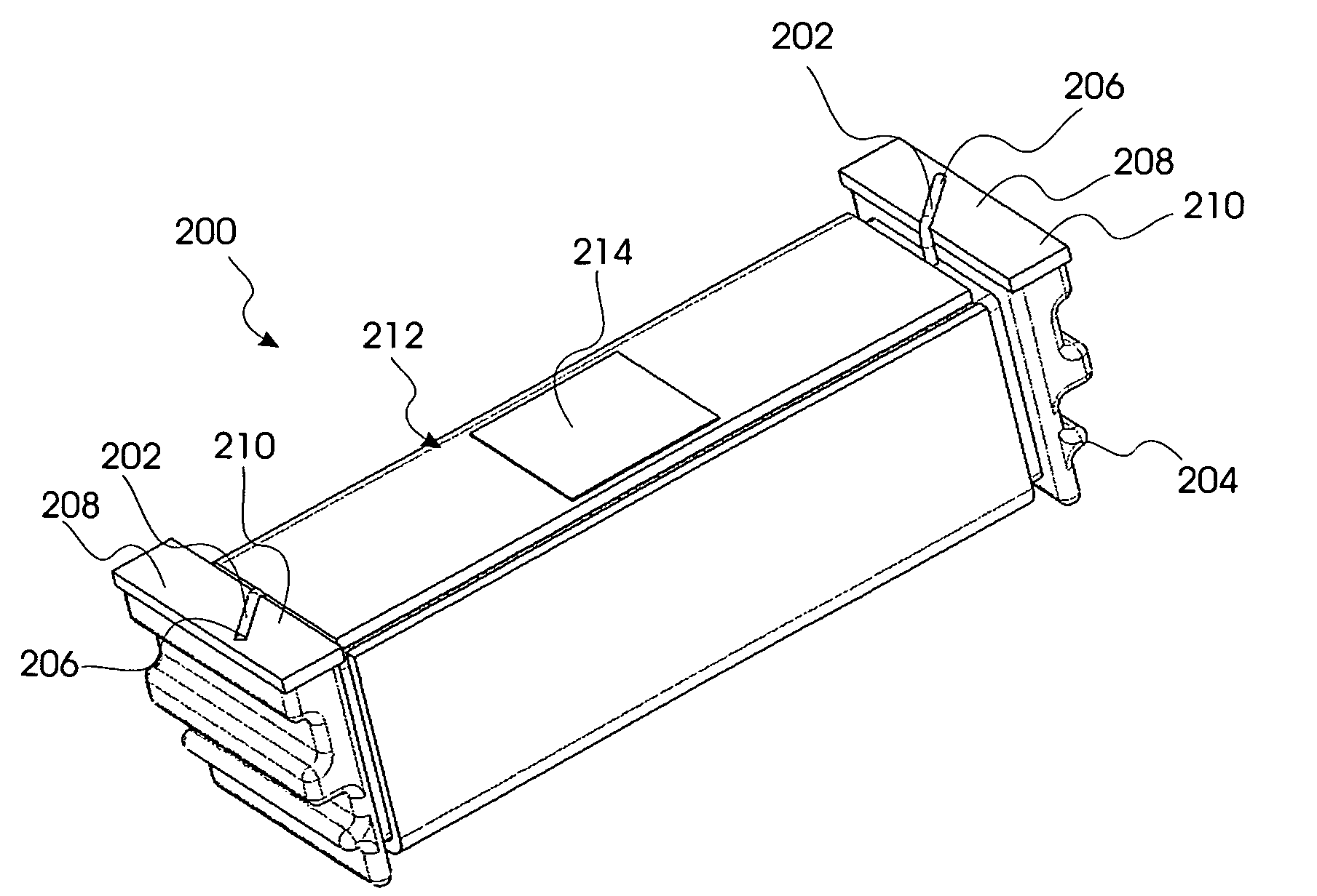
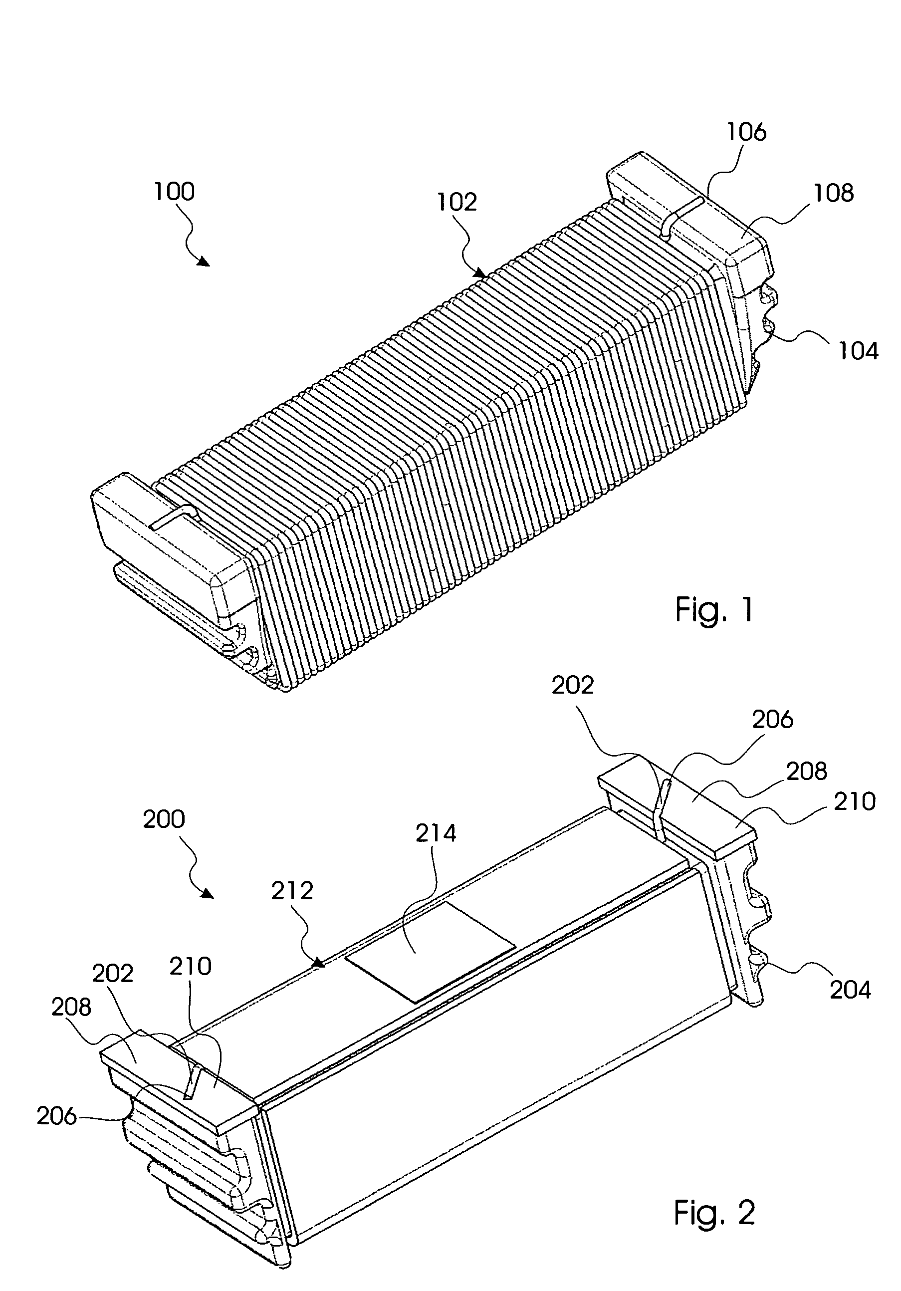
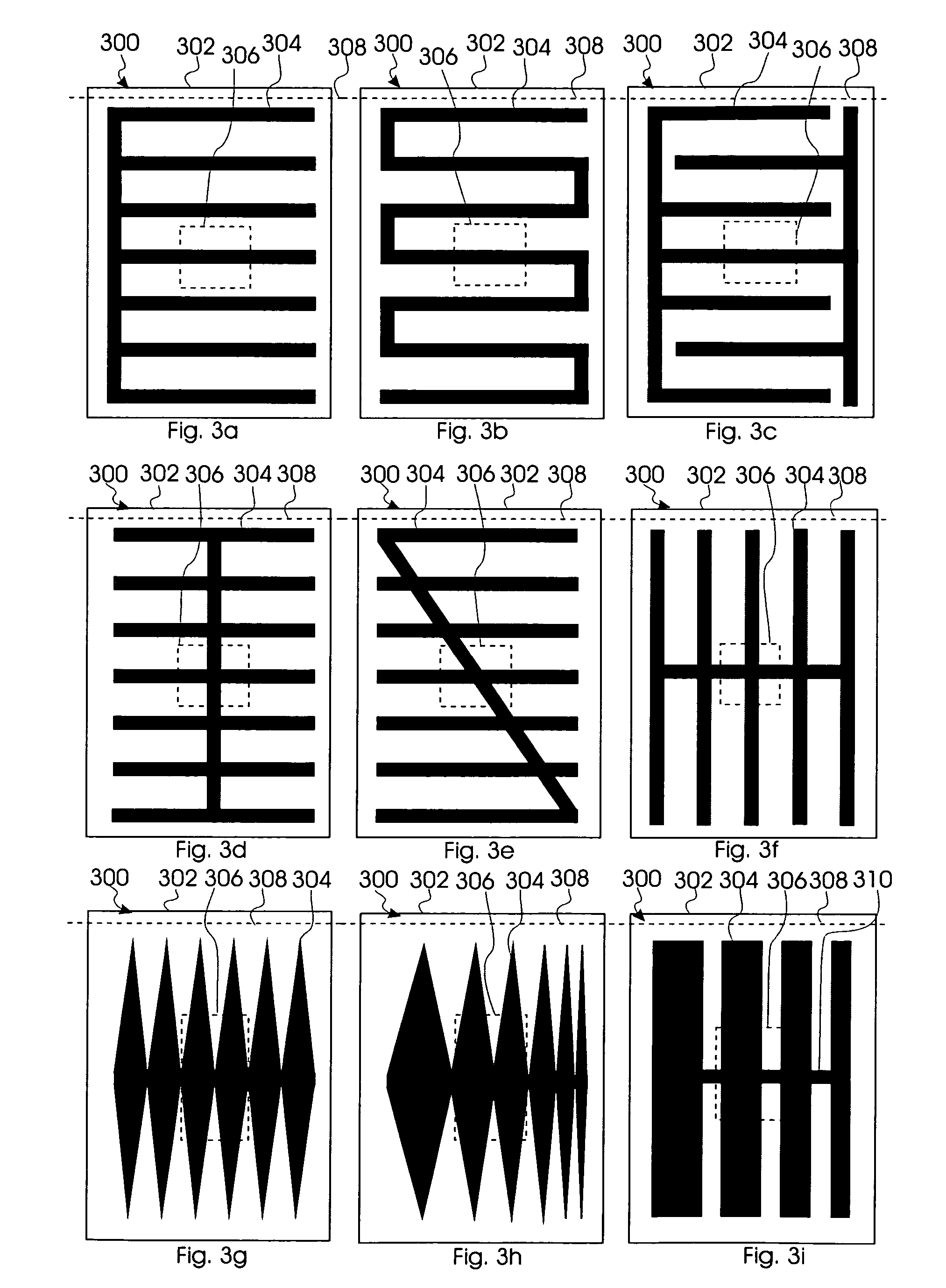
[0013] The above objects and advantage together with numerous other objects, advantages and features, which will become evident from below detailed description, are obtained according to a first aspect of the present invention by a surface mounted coil antenna for wireless communication, and comprising a wire wounded about a core thereby establishing a plurality of windings and having its ends connected to mounting sections at each end of said core, and wherein said surface mounted coil further comprising a shielding layer provided between mounting sections thereby covering said windings, said shielding layer comprising a shielding pattern and a contact section for connecting to a reference level and to said shielding pattern.
[0014] The term “reference level” is in this context to be construed as a signal reference such as a ground level or zero level.
[0015] The core according to the first aspect of the present invention may comprise soft-magnetic material, such as ferrite. It is particularly advantageous that the coil is manufactured in as few parts as possible, and thus by injection moulding the entire core including the mounting sections in a soft-magnetic material reduces the number of parts required. In this manner the production requirements are simplified and the production cost thereby reduced.
[0016] The coil according to the first aspect of the present invention may have an axial length in the range of 1 to 10 mm, such as between 2 and 9 mm, between 3 and 8 mm, between 4 and 7 mm, or between 5 and 6 mm, or such between 1 and 3 mm, between 3 and 5 mm, between 5 and 7 mm, or between 7 and 10 mm. The coil may thus advantageously be used in a hearing aid for enabling wireless communication between a set of hearing aids or between an accessory device and a hearing aid.
[0017] The shielding layer according to the first aspect of the present invention may comprise a flexible substrate, printed circuit board, printed wired board, or any combination thereof. Alternatively, the shielding layer may comprise a non-conducting layer provided between mounting sections thereby covering the windings and a conducting layer comprising the shielding pattern. The non-conducting layer may be established by a fluidized bed process, by chemical vapour deposition of polymers such as Parylene, by dip coating, by spray coating, by electrochemical deposition or by a printing process, such as a jet or laser process. The conducting layer may be established by non-selective electrochemical deposition followed by physical or chemical structuring, by selective electrochemical deposition, by non-selective chemical or physical vapour deposition followed by physical or chemical structuring or by similar additive manufacturing or general masking techniques.

Problems solved by technology

In particular in hearing aids inductive coupling is utilised as a wireless transmission means due to minimal power and space available in hearing aids.
However, the loop antenna described in the International patent application is of considerable size.
Thus the loop antenna is not suitable for implementation in small sized consumer goods such as a hearing aid.
In addition, the shield applied in the loop antenna is complicated to accomplish in fabrication of small and delicate sized antennas.

Method used


Image

  • Shielded coil for inductive wireless applications
  • Shielded coil for inductive wireless applications
  • Shielded coil for inductive wireless applications

Examples


Embodiment Construction

[0035] In the following description of the various embodiments, reference is made to the accompanying figures, which show by way of illustration how the invention may be practiced. It is to be understood that other embodiments may be utilized and structural and functional modifications may be made without departing from the scope of the present invention.

[0036]FIG. 1, shows a coil 100 for inductive wireless transmission. The coil 100 comprises a wire 102 wound about a central portion of a core 104. The wire forms a series of loops which when placed in a magnetic field experience induced electromotive force causing a current to flow from one end of the coil to the other and generating a voltage, for example as used during reception, or when excited by a driving current causing a magnetic field to be induced, for example as used during transmission. The core 104 is made of a soft-magnetic material, such as ferrite, with high permeability and narrow hysteresis thus allowing a high mag...


PUM


Abstract

The present invention relates to a surface mounted coil (200) for wireless communication. The coil (200) comprises a wire (202) wounded about a core (204) thereby establishing a plurality of windings and having its ends terminated on mounting sections (208) at each end of the core (204). The coil (200) further comprises a shielding layer (212, 300) wound about a central part of the core (204) thereby covering said windings. The shielding layer (212, 300) comprises a shielding pattern and a contact section (214) for connecting to a ground level and to the shielding pattern.

Description

FIELD OF INVENTION [0001] This invention relates to a shielded coil for wireless applications such as between a set of hearing aids or between a hearing aid and an accessory device. BACKGROUND OF INVENTION [0002] Near field wireless transmission is increasingly becoming a required feature in a wide variety of consumer goods as well as medical instruments such as for example hearing aids. [0003] In particular in hearing aids inductive coupling is utilised as a wireless transmission means due to minimal power and space available in hearing aids. Therefore miniature coils are incorporated in hearing aids enabling communication either between associated hearing aids or between hearing aids and a remote controller. [0004] German patent no.: DE 198 18 040 discloses a surface mounted device (SMD) coil comprising a duroplastic supporting body with a recess for receiving a flat soldering wire, wherein the flat soldering wire is pressed into the recess ensuring that the flat soldering wire ca...

Claims


Application Information

Patent Timeline
Patent Type & Authority Applications(United States)
IPC IPC(8): H01Q7/08H01Q5/40
CPCH01F27/292H01F27/362H01Q1/273H01Q1/44H01Q5/40H01Q7/08H04R2225/51H01F38/14H01Q1/52B33Y80/00H01F27/36H01F27/363
Inventor MULLENBORG, MATTHIASRASMUSSEN, FRANK ENGELESSABAR, MOHAMADOLLGAARD, MOGENSNIELSEN, CHRISTIAN
Owner OTICON
Learn More