
Liquid crystal display and driving method thereof

a technology of liquid crystal cells and driving methods, applied in non-linear optics, static indicating devices, instruments, etc., can solve the problem that liquid crystal cells cannot sustain their bend states, and achieve the effect of ensuring driving stability

Inactive Publication Date: 2007-05-24
SAMSUNG DISPLAY CO LTD
View PDF5 Cites 13 Cited by
  • Summary
  • Abstract
  • Description
  • Claims
  • Application Information

AI Technical Summary

Benefits of technology

[0012] Accordingly, it is an aspect of the present invention to provide an LCD wherein driving stability can be secured and a driving method for such an LCD.
[0015] A second aspect of the present invention provides a method of driving an LCD, the method including displaying an image from OCB mode liquid crystal cells formed within an effective display region, and applying a voltage larger than a transition voltage to liquid crystal in each dummy liquid crystal cell formed within a non-display region when an image is displayed from the liquid crystal cells. The non-display region may surround the display region allowing the dummy liquid crystal cells to impose an electric field upon the liquid crystal cells within the display region.

Problems solved by technology

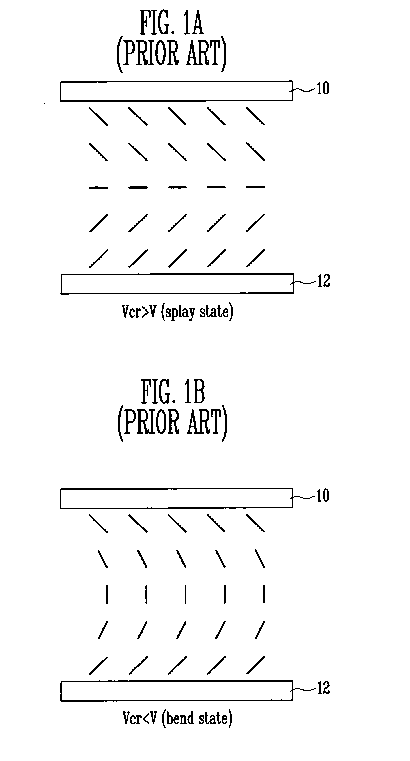
It can be speculated that these liquid crystal cells do not sustain their bend states because the liquid crystal cells located at the outermost edges of the LCD panel are not affected by the surrounding electric field.

Method used


Image

  • Liquid crystal display and driving method thereof
  • Liquid crystal display and driving method thereof
  • Liquid crystal display and driving method thereof

Examples


first embodiment

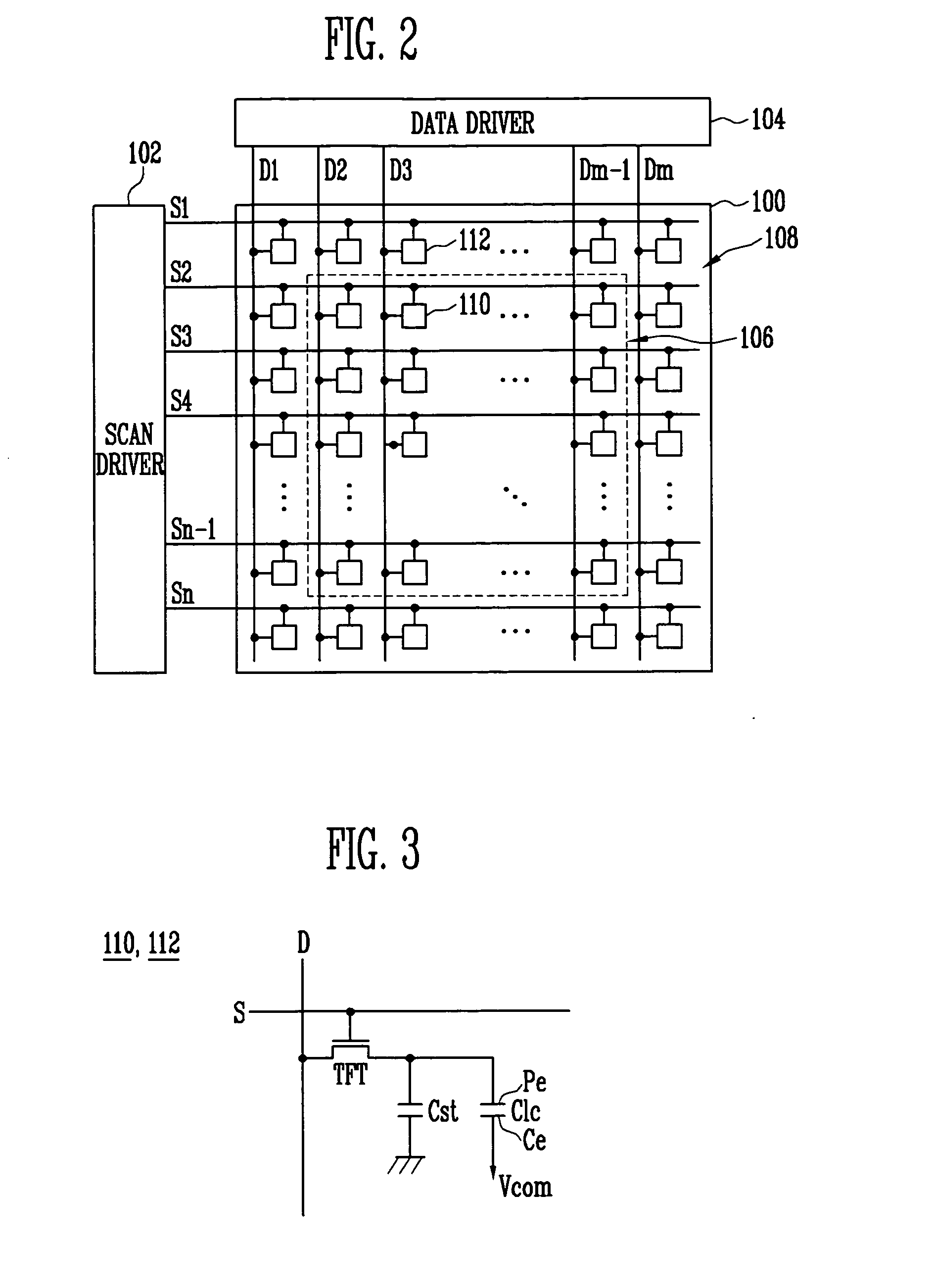
[0025]FIG. 2 is a block diagram of an OCB mode LCD according to the present invention.

[0026] Referring to FIG. 2, the OCB mode LCD according to the first embodiment of the present invention includes an LCD panel 100, a data driver 104 for applying data signals to data lines D1 to Dm of the LCD panel 100 and a scan driver 102 for applying scan signals to scan lines S1 to Sn of the LCD panel 100.

[0027] In the embodiment of FIG. 2, the scan driver 102 and the data driver 104 are shown to be separated from each other. However, the two drivers 102 and 104 may form a single integrated circuit (IC) as a Chip On Glass (COG). A circuit including both the scan driver 102 and the data driver 104 may be referred to as a panel driver.

[0028] The scan driver 102 applies the scan signals to the scan lines S1 to Sn. Accordingly, dummy liquid crystal cells 112 and liquid crystal cells 110 are selected by the horizontal lines.

[0029] The data driver 104 converts data input from the outside into the ...

second embodiment

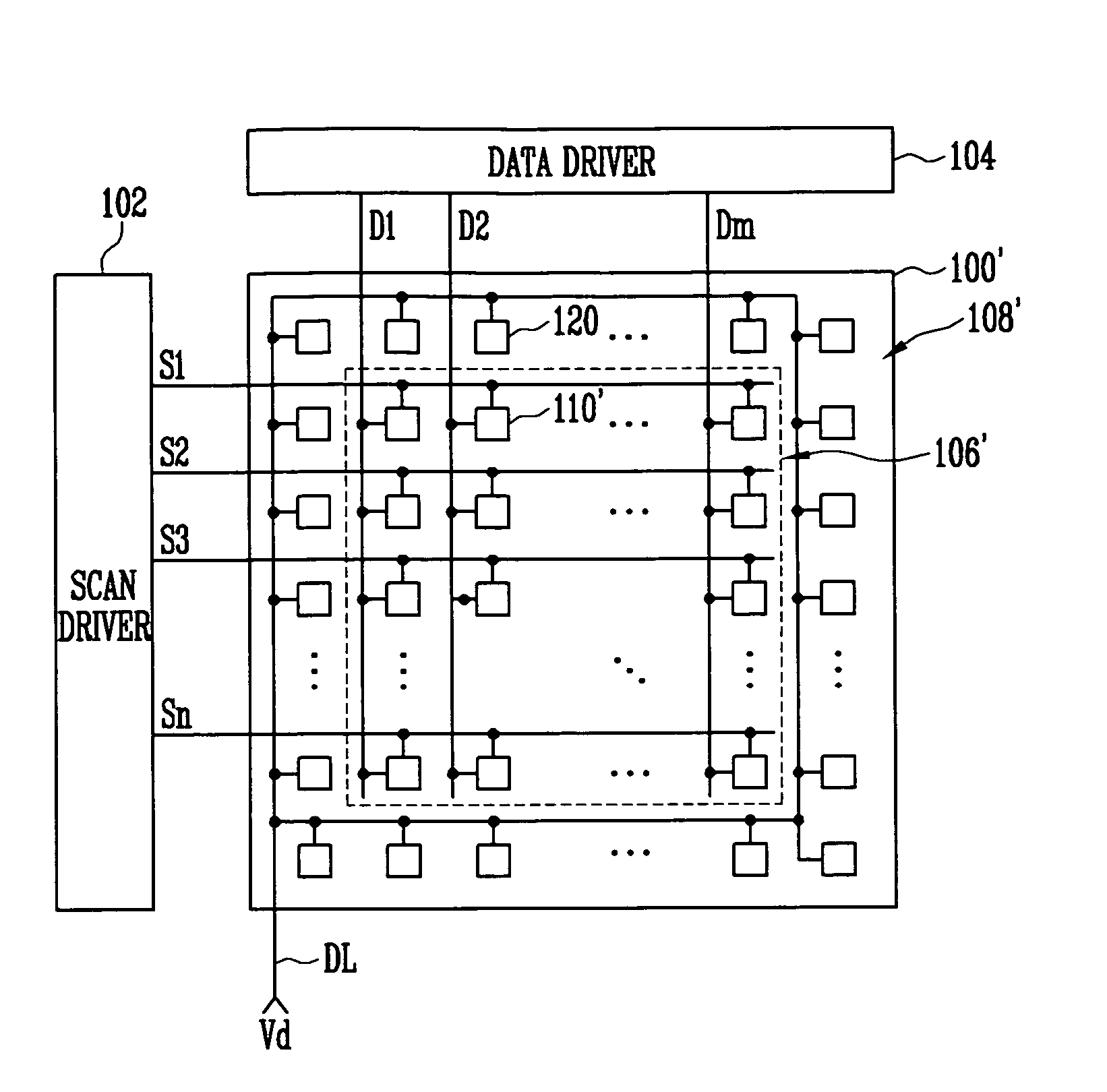
[0037]FIG. 4 is a block diagram of an OCB mode LCD according to the present invention. When describing FIG. 4, like elements to the elements shown in FIG. 2 are designated by like reference numerals and their detailed description is omitted.

[0038] Referring to FIG. 4, the OCB mode LCD of the second embodiment includes an LCD panel 100′, a data driver 104 for applying the data signals to data lines Dl to Dm of the LCD panel 100′ and a scan driver 102 for applying scan signals to scan lines S1 to Sn of the LCD panel 100′.

[0039] In an effective display region 106′, liquid crystal cells 110′ are formed. Each of the liquid crystal cells 110′ displays a portion of the image corresponding to a data signal applied thereto. The liquid crystal cells 110′ are similar to the liquid crystal cells 110 of the first embodiment.

[0040] In a non-display region 108′ of the LCD panel 100′, dummy liquid crystal cells 120 are arranged to surround the liquid crystal cells 110′. A voltage larger than the ...


PUM


Abstract

Disclosed is a liquid crystal display (LCD) wherein driving stability is secured. The LCD includes Optically Compensated Birefringence (OCB) mode liquid crystal cells formed where a data line and a scan line cross over within a display region of an LCD panel, a panel driver for driving the data and the scan lines, and OCB mode dummy liquid crystal cells formed within a non-display region of the LCD panel to surround the liquid crystal cells. Liquid crystal in each of the dummy liquid crystal cells sustains a bend state when the liquid crystal cells in the display region are driven corresponding to a data signal applied from the data line.

Description

CROSS-REFERENCE TO RELATED APPLICATION [0001] This application claims priority to and the benefit of Korean Patent Application No. 10-2005-0112575, filed on Nov. 23, 2005, in the Korean Intellectual Property Office, the entire content of which is incorporated herein by reference. BACKGROUND [0002] 1. Field of the Invention [0003] The present invention relates to a liquid crystal display (LCD) and a driving method thereof, and more particularly, to an LCD wherein driving stability can be secured and a driving method for such an LCD. [0004] 2. Discussion of Related Art [0005] In recent years, various types of flat panel displays that have a lower weight and volume than cathode ray tubes (CRTs) have been developed. Liquid crystal displays (LCDs), field emission displays (FEDs), plasma display panels (PDPs), organic light emitting displays (OLEDs) and the like are used as flat panel displays. [0006] Since LCDs have advantages in terms of miniaturization, lightweight, low power consumpti...

Claims


Application Information

Patent Timeline
IPC IPC(8): G09G3/36
CPCG09G3/3611G09G2300/0413G09G2300/0491G09G2310/0232G09G3/36G02F1/133
Inventor PARK, JIN WOO
Owner SAMSUNG DISPLAY CO LTD
Learn More