
Configuration detection device for endoscope

a technology of configuration detection and endoscope, which is applied in the field of configuration detection device for detecting a configuration of an endoscope, can solve the problems of reducing the accuracy of configuration detection, x-ray exposure may have negative effects on body health, and configuration may not be suitable,

Inactive Publication Date: 2007-05-24
HOYA CORP
View PDF16 Cites 75 Cited by
  • Summary
  • Abstract
  • Description
  • Claims
  • Application Information

AI Technical Summary

Benefits of technology

The present invention provides a configuration detection device for an endoscope that can detect its configuration with high precision. The device includes a light-providing optical fiber, a light reflector, a curvature-detecting optical fiber, and a light modulator. The light modulator modulates the reflected light from the endoscope in real-time, and the configuration detection device detects the configuration of the endoscope based on the strength or wavelength of the reflected light and its distance from the light modulator. The invention also includes a light source, a fiber bundle, a light detector, and an image display for easy visualization of the endoscope's configuration.

Problems solved by technology

X-ray exposure may have negative effects on body health when the degree of exposure is over a permissible amount.
On the other hand, if magnetism is used for detecting the configuration of an inserted scope, then if the subject is out of range of the magnetic field, the configuration may not be detected, or the accuracy of detection of the configuration may decrease.
When adopting an aforementioned optical configuration detector probe to detect a configuration of an inserted scope, the choice of endoscope to use with such an optical configuration detector probe is limited.
Therefore, an optical configuration detector probe can not be adopted to detect a configuration of an inserted scope without narrowing the diameter thereof in order to adjust the diameter of the associated forceps mouth.

Method used


Image

  • Configuration detection device for endoscope
  • Configuration detection device for endoscope
  • Configuration detection device for endoscope

Examples


Embodiment Construction

[0043] Hereinafter, the preferred embodiments of the present invention are described with reference to the attached drawings.

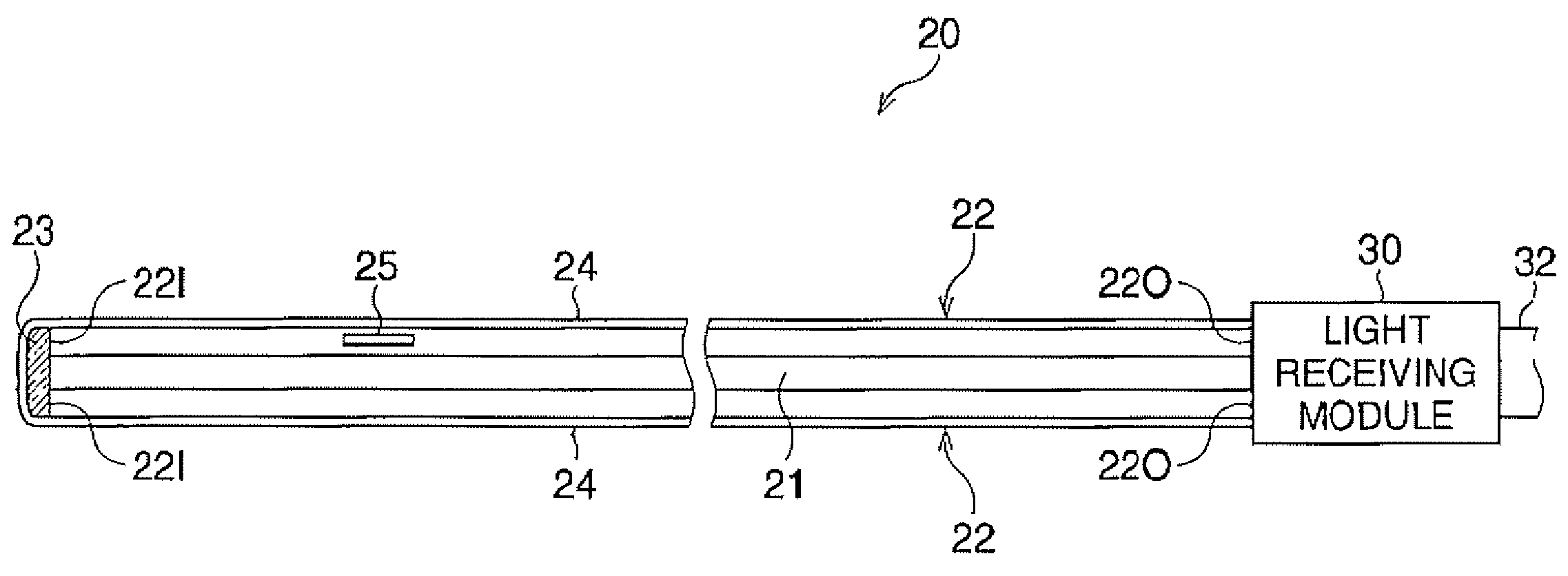
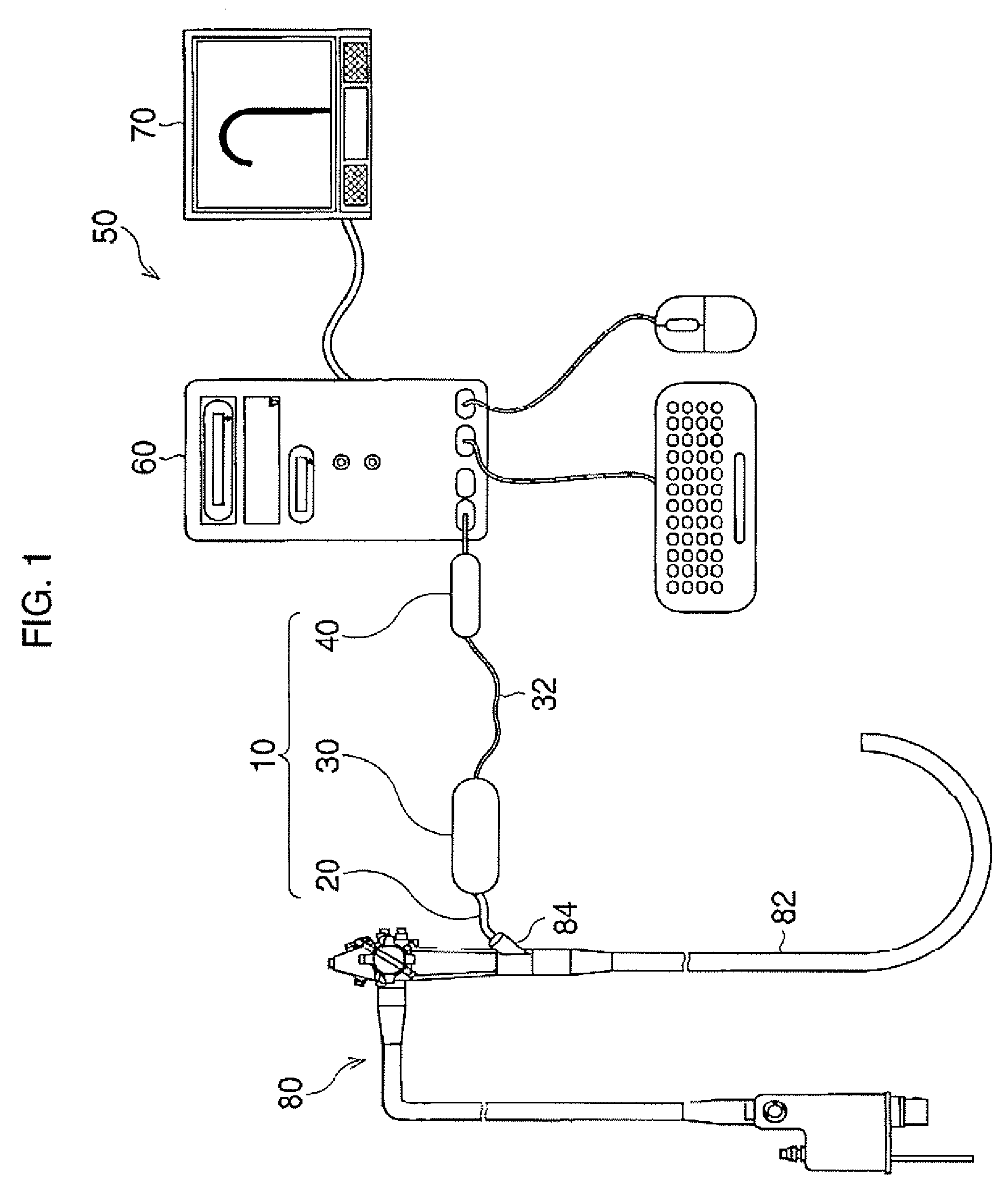
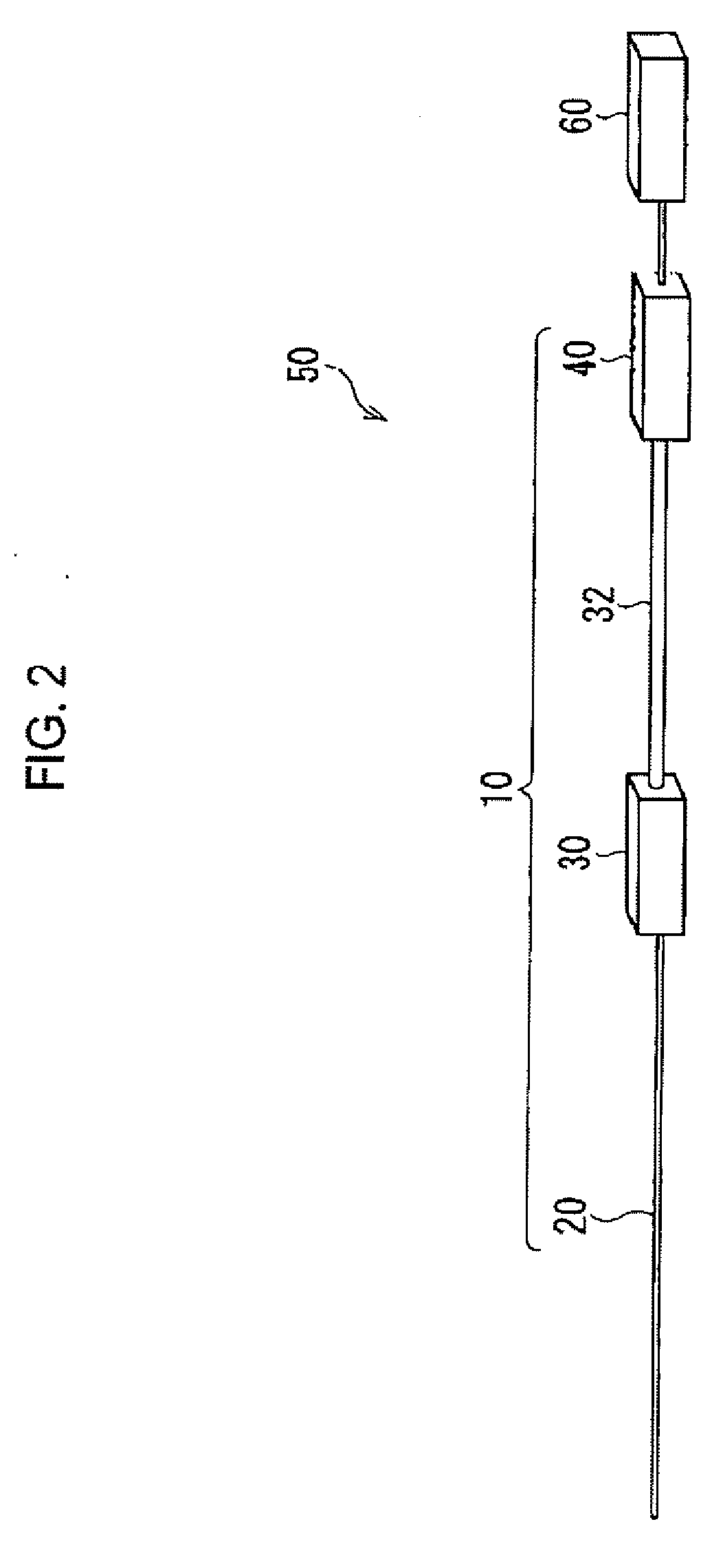
[0044] As shown in FIGS. 1 and 2, in the configuration detection system 50 of the first embodiment, an endoscope detector probe 10, an image processing device 60, and a monitor 70 are provided. The endoscope detector probe 10 includes a fiber bundle 20, a light receiving module 30, and a connector 40, The fiber bundle 20 is connected to the light receiving module 30, and the light receiving module 30 is connected to the connector 40 via a cable 32.

[0045] The configuration detection system 50 is used for detecting a configuration of an insertion section 82 that is provided at the end of a scope 80, and that is inserted into a body of a subject person. That is, first, the fiber bundle 20 is inserted into the scope 80 through a forceps channel 84, to be flexible together with the insertion section 82. Signals representing the curvature of the fiber bundle 20 ar...


PUM


Abstract

A configuration detection device includes a light-providing optical fiber, a light reflector a curvature-detecting optical fiber, and a light modulator. The light-providing optical fiber transmits detection light in a plurality of wavelength ranges that have different wavelengths from one another, The light reflector reflects the detection light as reflected light. The curvature-detecting optical fiber transmits the reflected light, and is bent together with an endoscope. The light modulator modulates at least one of the strength or the wavelength of the reflected light for each of the wavelength ranges. Based on at least one of the strength or the wavelength of the reflected light that is pre-modulated and post-modulated, and based on the distance between the light modulator and the output end of the curvature-detecting optical fiber, the configuration of the endoscope is detectable.

Description

BACKGROUND OF THE INVENTION [0001] 1. Field of the Invention [0002] The present invention relates to a configuration detection device for detecting a configuration of an endoscope, especially for detecting a configuration of an endoscope that is inserted into a body for an observation. [0003] 2. Description of the Related Art [0004] In a medical endoscopic observation, an endoscope must be inserted into a body in accordance with the shapes of body organs that are to be examined, because the end of the endoscope should not come into contact with them. [0005] Therefore, an endoscope inspection system where a configuration of a scope inserted into a body is confirmed in an X-ray transmitted image generated by transmission of an X-ray to a subject, during an endoscopic observation, has been known. Further, a detection device for detecting a configuration of an inserted scope, where a configuration of a scope inside a body is detected by finding a change of a magnetic field, using a magn...

Claims


Application Information

Patent Timeline
Patent Type & Authority Applications(United States)
IPC IPC(8): G02B6/06
CPCA61B5/06A61B5/065A61B1/009
Inventor KOBAYASHI, SHOTARO
Owner HOYA CORP
Learn More