Adjustable bone screw assembly

a bone screw and adjustment technology, applied in the field of bone screw, can solve the problems of inability to adjust the screw shank relative to the screw head, inability to move the screw shank in a plane in which movement is not desirable, prior art bone screw systems are not optimized for non-fusion systems, etc., to achieve sufficient adjustability, reduce the distance between the center and the screw, and reduce the moment applied

Active Publication Date: 2007-05-24
DEPUY SPINE INC (US)
View PDF47 Cites 181 Cited by
  • Summary
  • Abstract
  • Description
  • Claims
  • Application Information

AI Technical Summary

Benefits of technology

[0010] The present invention provides an adjustable bone screw assembly that provides for controlled adjustment of a spinal connection element, such as a spinal rod, received in a body of the bone screw assembly relative to the body of the bone screw. The adjustable bone screw assembly may allow the spinal connection element received in a receiving portion of the assembly to pivot in at least two directions about two different axes, while limiting movement in other selected directions. In addition, the bone screw assembly may reduce a distance between a center of a rod connected to the bone screw assembly and the vertebral bone surface secured by the bone screw assembly. The adjustable bone screw assembly thus allows for sufficient adjustability for rod placement and orientation, while reducing the moment applied on the screw.

Problems solved by technology

Polyaxial and multi-axial screws, which allow the screw shank to pivot in all directions about the head portion, can be difficult to control and often result in movement of the screw shank in planes in which movement is not desirable.
For example, during vertebral body rotation maneuvers, which require application of force to the screw head, it is not desirable for the screw shank to move relative to the screw head.
In addition, prior art bone screw systems are not optimized for non-fusion systems, which may employ flexible rods.
Without the support of fused bones, non-fusion systems must withstand the applied load for a longer time, even for the lifetime of a patient.
An additional complication of non-fusion stabilization systems is a loosening between the screw and bone.
Monoaxial and polyaxial screws of the prior art tend to have a relatively large distance between the center of the rod and the vertebral body surface, resulting in a relatively large moment applied to the screw body by the rod when the screw is implanted, leading to loosening and / or breakage.

Method used


Image

  • Adjustable bone screw assembly
  • Adjustable bone screw assembly
  • Adjustable bone screw assembly

Examples


Embodiment Construction

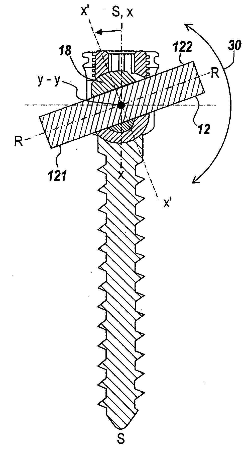
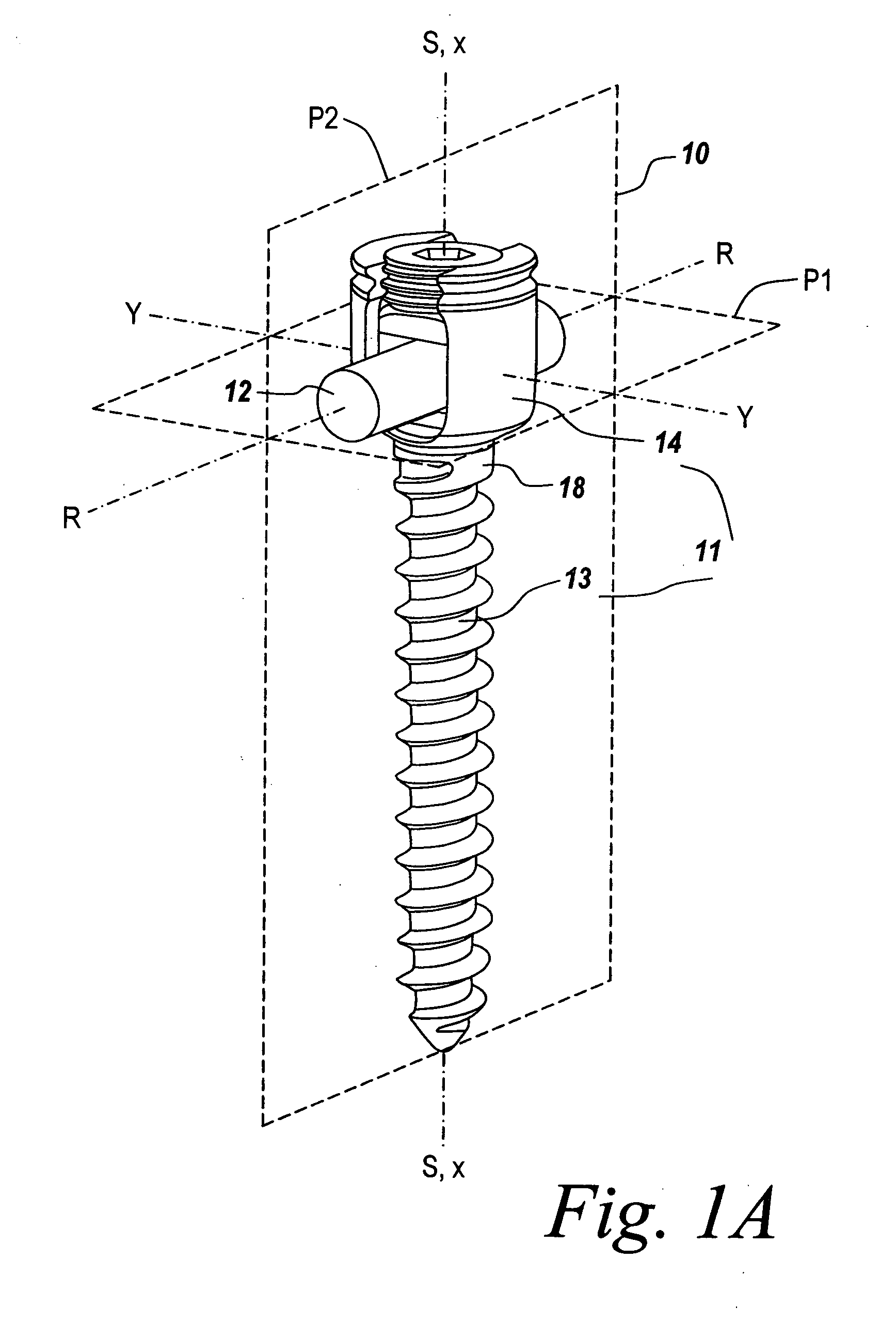
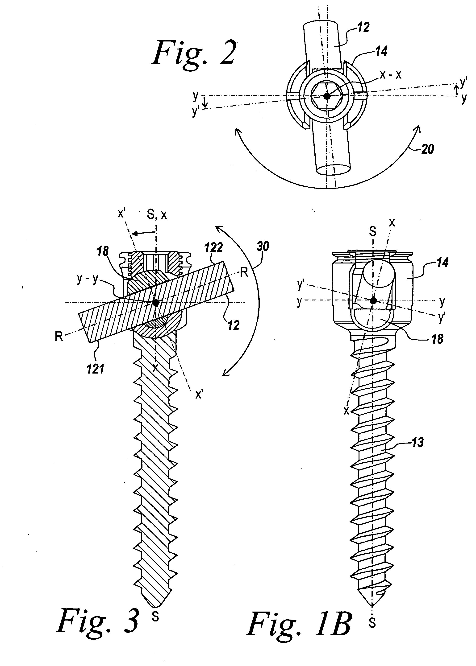
[0034] The present invention provides an improved bone screw assembly in a spinal connection system. One skilled in the art will recognize that the invention is not limited to use in bone or in spinal surgery, and that the instrument and methods described herein can be adapted for use with any suitable surgical device to be moved into a selected position in a variety of medical procedures. The present invention will be described below relative to certain exemplary embodiments to provide an overall understanding of the principles of the structure, function, manufacture, and use of the instruments disclosed herein. Those skilled in the art will appreciate that the present invention may be implemented in a number of different applications and embodiments and is not specifically limited in its application to the particular embodiments depicted herein.

[0035] During spinal deformity surgeries, it may be necessary to de-rotate the vertebral bodies to normalize the spine. Due to varying pa...


PUM


Abstract

A bone screw assembly includes a screw body, including anchor portion and rod-receiving portion, and a rod seat movably mounted in the screw body to allow for controlled angulation between a spinal connection element disposed in the rod seat and the screw body. The rod seat is pivotable in one or more selected directions about one or more axes relative to the screw body. The rod seat may include a first lower rod seat element disposed in a recess of the screw body having a cylindrical bottom surface to facilitate pivoting in a first direction. A second lower rod seat element is stacked on the first lower rod seat element and has a conical bottom surface abutting a top surface of the first lower rod seat element to facilitate pivoting in a second direction.

Description

FIELD OF THE INVENTION [0001] The present invention relates to spinal connection devices used in orthopedic surgery. More particularly, the present invention relates to a bone screw for coupling a spinal rod to a bone, such as the pedicle. BACKGROUND OF THE INVENTION [0002] Spinal fixation systems may be used in surgery to align, adjust and / or fix portions of the spinal column, i.e., vertebrae, in a desired spatial relationship relative to each other. Many spinal fixation systems employ a spinal rod for supporting the spine and for properly positioning components of the spine for various treatment purposes. Vertebral anchors, comprising pins, bolts, screws, and hooks, engage the vertebrae and connect the supporting rod to different vertebrae. The size, length and shape of the cylindrical rod depend on the size, number and position of the vertebrae to be held in a desired spatial relationship relative to each other by the apparatus. [0003] Spinal fixation elements can be anchored to ...

Claims


Application Information

Patent Timeline
Patent Type & Authority Applications(United States)
IPC IPC(8): A61F2/30
CPCA61B17/7032A61B17/7037A61B17/7001
Inventor KWAK, SEUNGKYU DANIELCHAO, NAM T.BURKE, ANDREA
Owner DEPUY SPINE INC (US)
Why Eureka
Try Eureka