System for controlled delivery of stents and grafts

a stent and graft technology, applied in the field of percutaneous transluminal vascular procedures, can solve the problems of traumatic, large diameter bulky grafts, difficult vasculature navigation, etc., and achieve the effects of less vascular vascular vascularity, less vascular vascularity, and less vascular vascularity

Inactive Publication Date: 2007-05-24
AGA MEDICAL CORP MS US
View PDF60 Cites 205 Cited by
  • Summary
  • Abstract
  • Description
  • Claims
  • Application Information

AI Technical Summary

Benefits of technology

[0018]FIG. 2 is a greatly enlarged view of the distal end portion of the assembly of FIG. 1 showing the proximal ends

Problems solved by technology

The large diameter bulky grafts are also more difficult to navigate through the vasculature and may be more traumatic to the vasculature due to their stiffness.
In some cases, a cut down through the skin to expose the artery is required, due to the sheath diameter being too large to access the artery in the normal manner using the Seldinger technique.
Another issue common to

Method used


Image

  • System for controlled delivery of stents and grafts
  • System for controlled delivery of stents and grafts
  • System for controlled delivery of stents and grafts

Examples


first embodiment

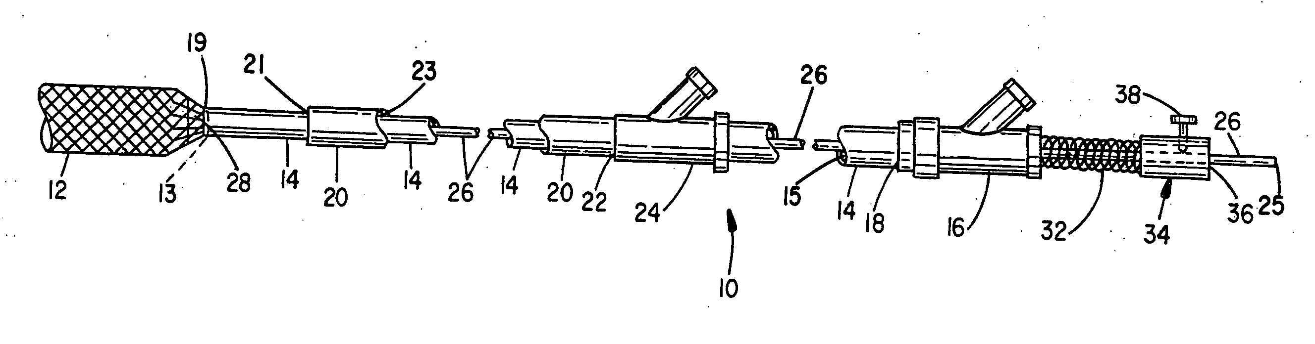
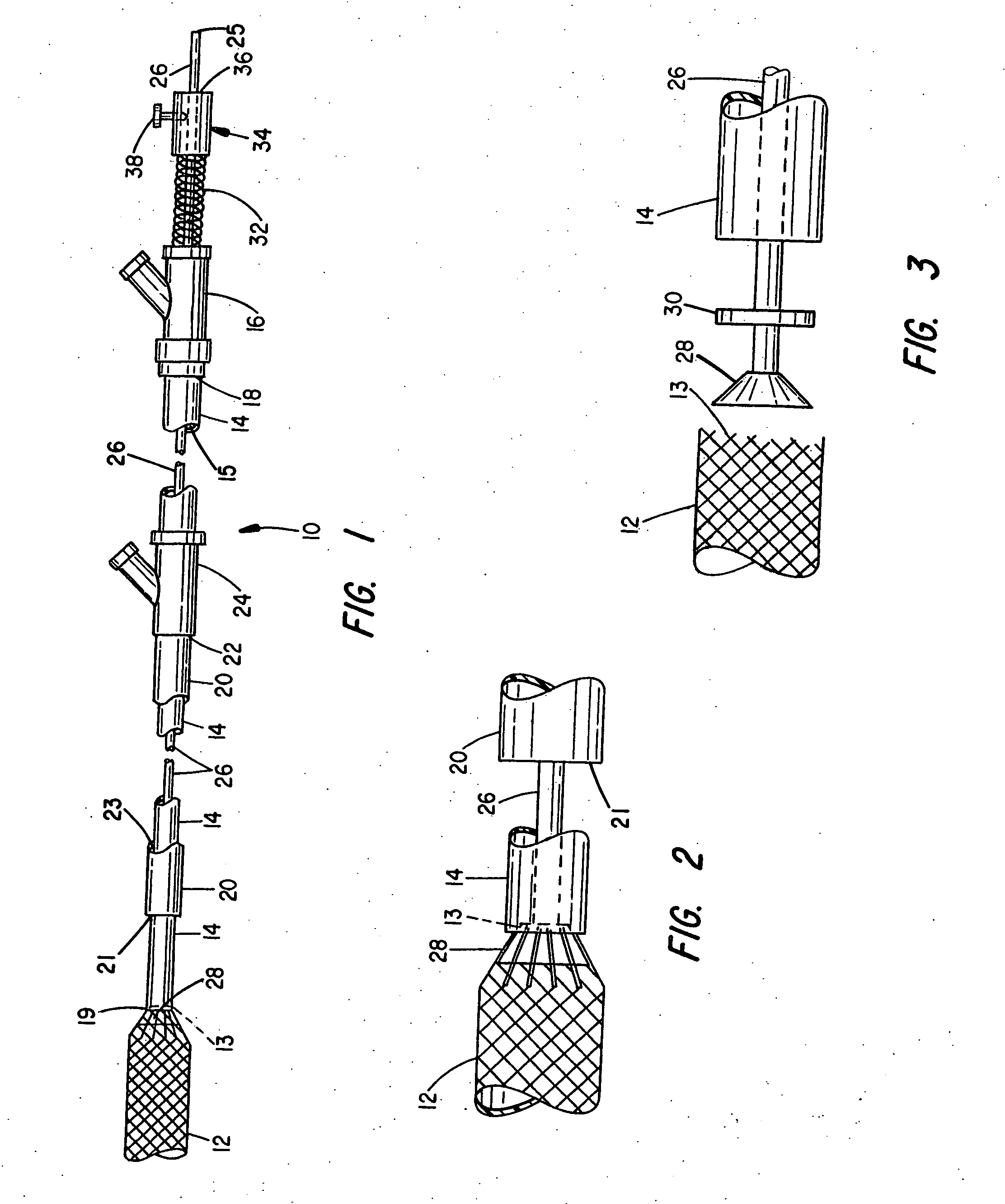
[0036] Turning next to the construction of the device, the prosthesis delivery apparatus 10 comprises: [0037] an outer tubular catheter 20 (also called a “guiding catheter”), having a distal end 21, a proximal end 22 and a lumen 23, extending there between with a Y adapter 24 on the proximal end in communication with the lumen; [0038] an inner tubular pusher catheter 14, also having a proximal end 18, a distal end 19, and a lumen 15, extending there between, and having an outer diameter sized to slidingly fit within the lumen of the outer tubular catheter 20 with a Y adapter 16 mounted to the proximal end in communication with the lumen; [0039] an elongate, flexible member 26, coaxially inserted through the lumen of the inner pusher catheter 14 and having a first bead member 28, and a washer like member 30, affixed to its distal end where the bead is sized to at least partially fit within the lumen of the inner pusher catheter at the distal end, and the washer 30, is sized to slidin...

third embodiment

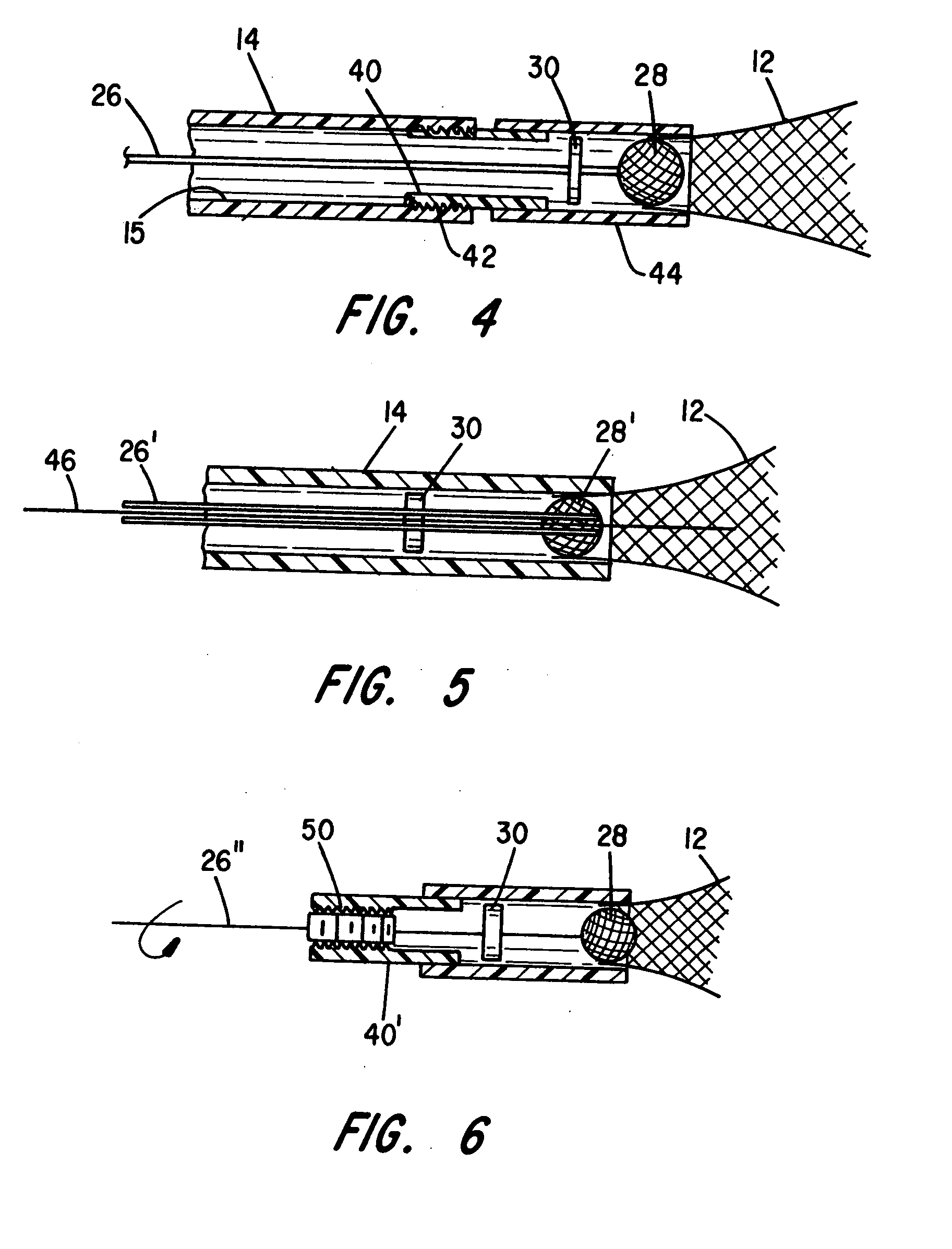
[0069] In the device 10 illustrated in FIG. 6, the bridge tube 40′ has a female thread 50 coaxially placed to engage a corresponding raised male thread on the elongate flexible member 26″. When the threads of member 26″ are engaged with the threads of bridge tube 40′, rotation by a handle (not shown) outside the body connected to the proximal end of member 26″ either advances or retracts member 26″ and, therefore, bead 28 to clamp or release the hold on the prosthesis 12.

[0070] While a preferred embodiment of the present invention has been described, it should be understood that various changes, adaptations and modifications may be made therein without departing from the spirit of the invention and the scope of the appended claims. For example, rather than front loading the pusher catheter 14 carrying the elongate member 26 and the prosthesis 12 by feeding the proximal end of the pusher catheter through the distal end of the delivery sheath 20 and then along the length of the delive...


PUM


Abstract

The present invention provides a delivery mechanism for percutaneously routing a stent or graft through the vascular system and procedures for addressing an aneurysm or an otherwise damaged vessel. The delivery system includes an outer tubular guide catheter 20, an inner tubular delivery (pusher) catheter 14 coaxially disposed and slidable relative to the outer guide catheter and an elongated flexible wire or cable 26 that is coaxially insertable through the lumen of the inner tubular catheter and that has a frusto-conical bead affixed at the distal end thereof which is sized to at least partially fit within the lumen of the inner pusher catheter when a proximally directed tension force is applied between the elongated flexible wire or cable 26 with respect to the pusher catheter 14. By inserting a compressed coil spring between a proximal end portion of the pusher catheter 14 and the proximal end portion of the cable 26, the requisite clamping force is maintained to secure the stent or graft to the distal end of the pusher catheter until the compression spring force is removed. With the stent or graft clamped to the distal end of the inner pusher catheter, it can be drawn within the lumen of the outer guide catheter for delivery therewith to the target site.

Description

BACKGROUND OF THE INVENTION [0001] I. Cross-Reference to Related Application [0002] The present application is a continuation-in-part of co-pending application Ser. No. 11 / 121,386, filed May 4, 2005, the entirety of which is incorporated herein by reference for any purpose. [0003] II. Field of the Invention [0004] This invention relates generally to percutaneous transluminal vascular procedures, and more particularly to delivery apparatus for placing a stent, a stent graft or a tubular graft at a desired target location within a subject's vascular system. [0005] III. Discussion of the Prior Art [0006] In the field of interventional cardiology, it is now becoming routine to treat stenotic lesions in the vascular system using balloon angioplasty to render more patent a partially occluded blood vessel and to attempt to thwart restenosis by placement of a stent at the site of the treated lesion. [0007] Stents used in these procedures must be capable of assuming a reduced diameter config...

Claims


Application Information

Patent Timeline
IPC IPC(8): A61F2/84A61F2/90
CPCA61F2/90A61F2/95A61M25/09A61M25/01
Inventor AMPLATZ, KURTOSLUND, JOHN C.RUSSO, PATRICK
Owner AGA MEDICAL CORP MS US
Why Eureka
Try Eureka