Turbo-lag compensation system having an ejector

a compensation system and lag technology, applied in the direction of machines/engines, valve arrangements, combustion engines, etc., can solve the problems of requiring significant packaging space in the vehicle, reducing the transient performance of the turbocharged engine, and allegedly unnecessary boost compensation, etc., to achieve effective utilization of compressed air, reduce air storage, and increase the effect of air storag

Inactive Publication Date: 2007-05-31
FORD GLOBAL TECH LLC
View PDF11 Cites 25 Cited by
  • Summary
  • Abstract
  • Description
  • Claims
  • Application Information

AI Technical Summary

Benefits of technology

[0008] In this way, it is possible to take advantage of the compression device to enable reduced air storage, while utilizing a nozzle to more effectively utilize the compressed air that is available. For example, when the supersonic air stream is mixed with a subsonic stream from the intake manifold, the total momentum of the two streams is combined and conserved, so that the velocity of the mixed stream, and consequently the stagnation pressure, is increased. Thus, it is possible to use energy of the pressured air stream to increase the flow from the lower pressure intake manifold. In this way, less pressured air may be used to achieve desired compensation, thus improving efficiency in the use of the compressed air and in the storage space needed.

Problems solved by technology

However, under dynamic driving conditions, the smaller turbocharged engine may have less transient performance than a larger, naturally aspirated engine.
With such a system, boost compensation is allegedly unnecessary.
However, the inventors herein have recognized disadvantages with each of the above approaches.
Further, the system required two tanks of about 12 inches in diameter each, thus requiring significant packaging space in the vehicle.

Method used


Image

  • Turbo-lag compensation system having an ejector
  • Turbo-lag compensation system having an ejector
  • Turbo-lag compensation system having an ejector

Examples


Embodiment Construction

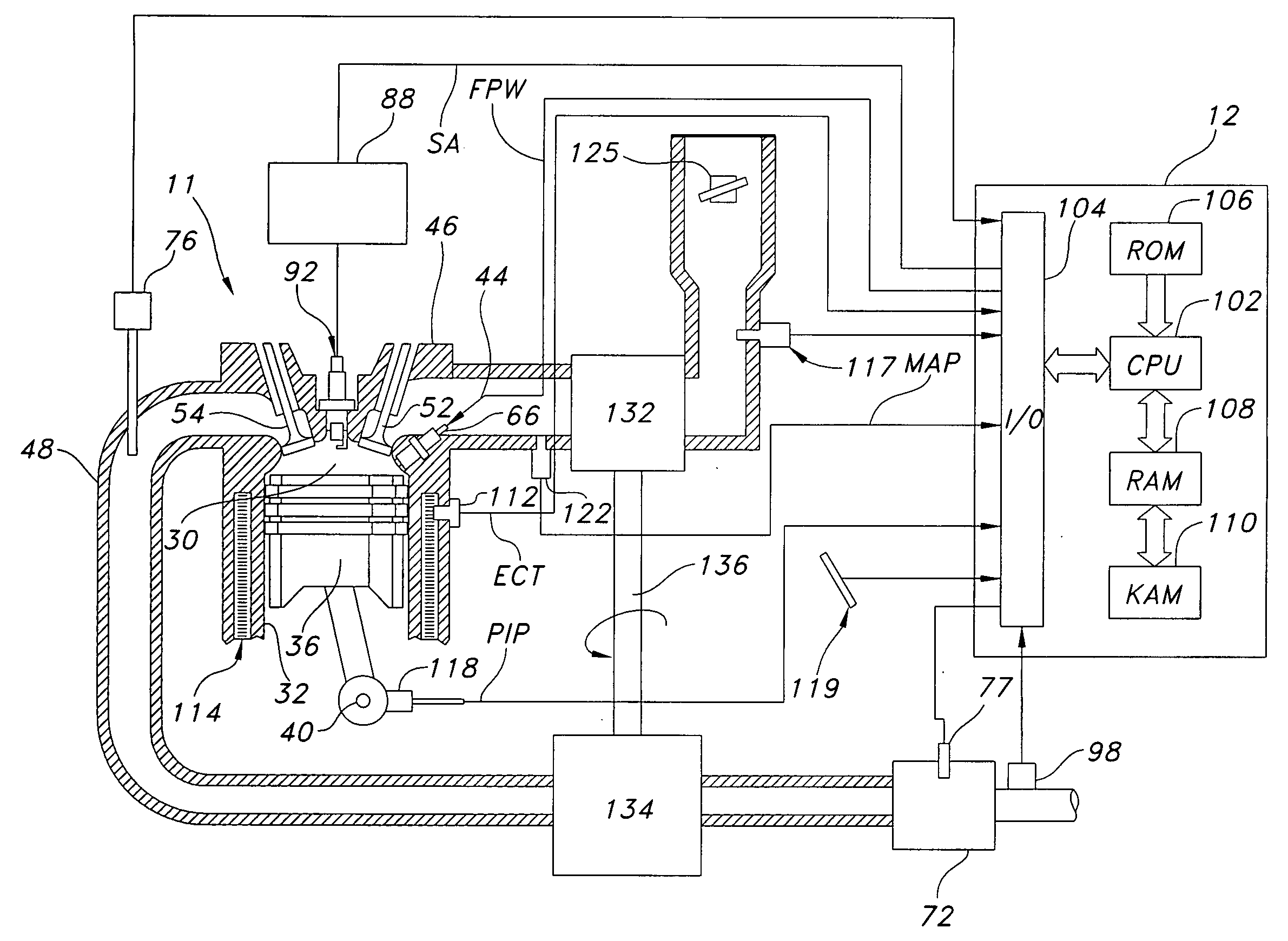
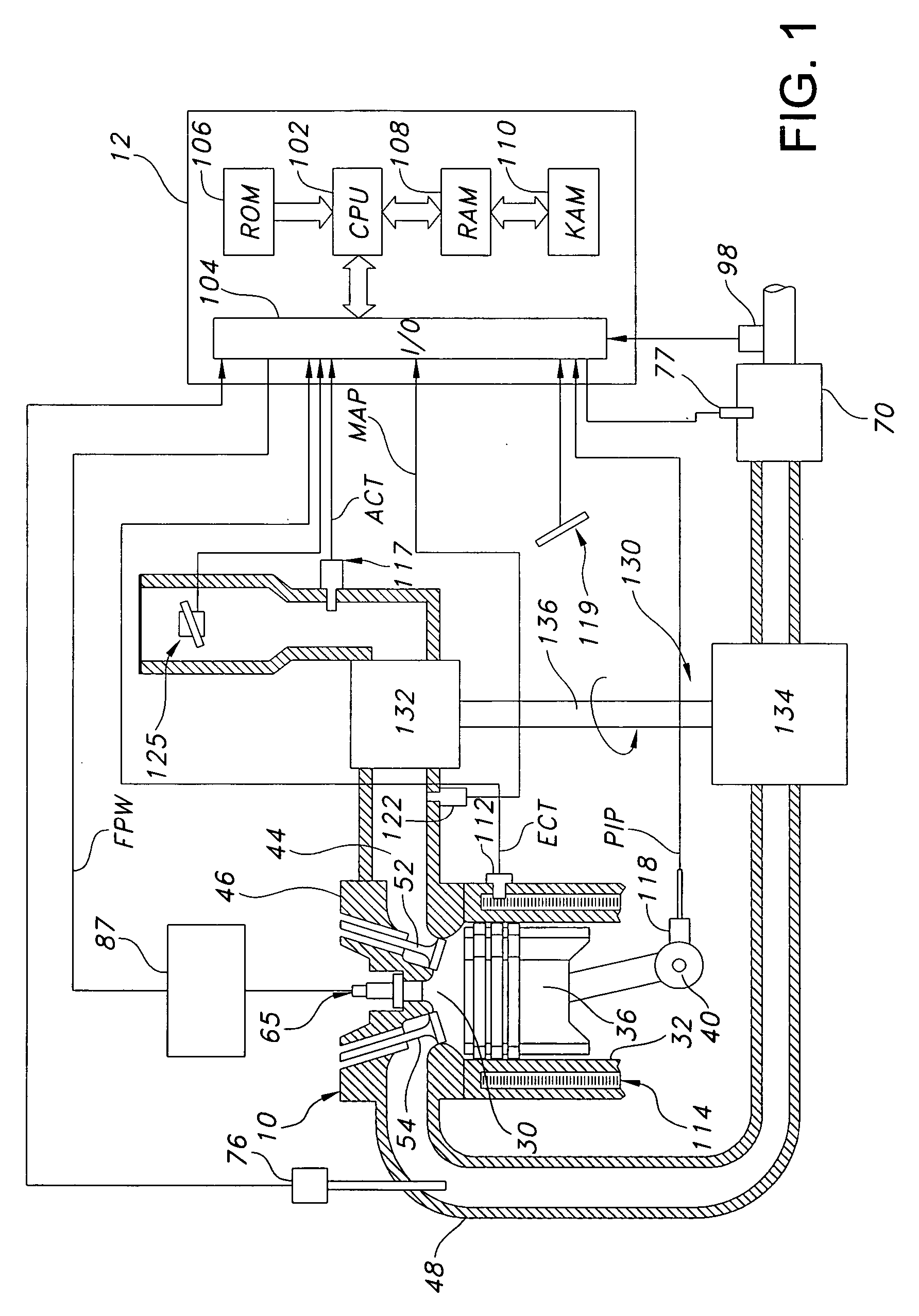
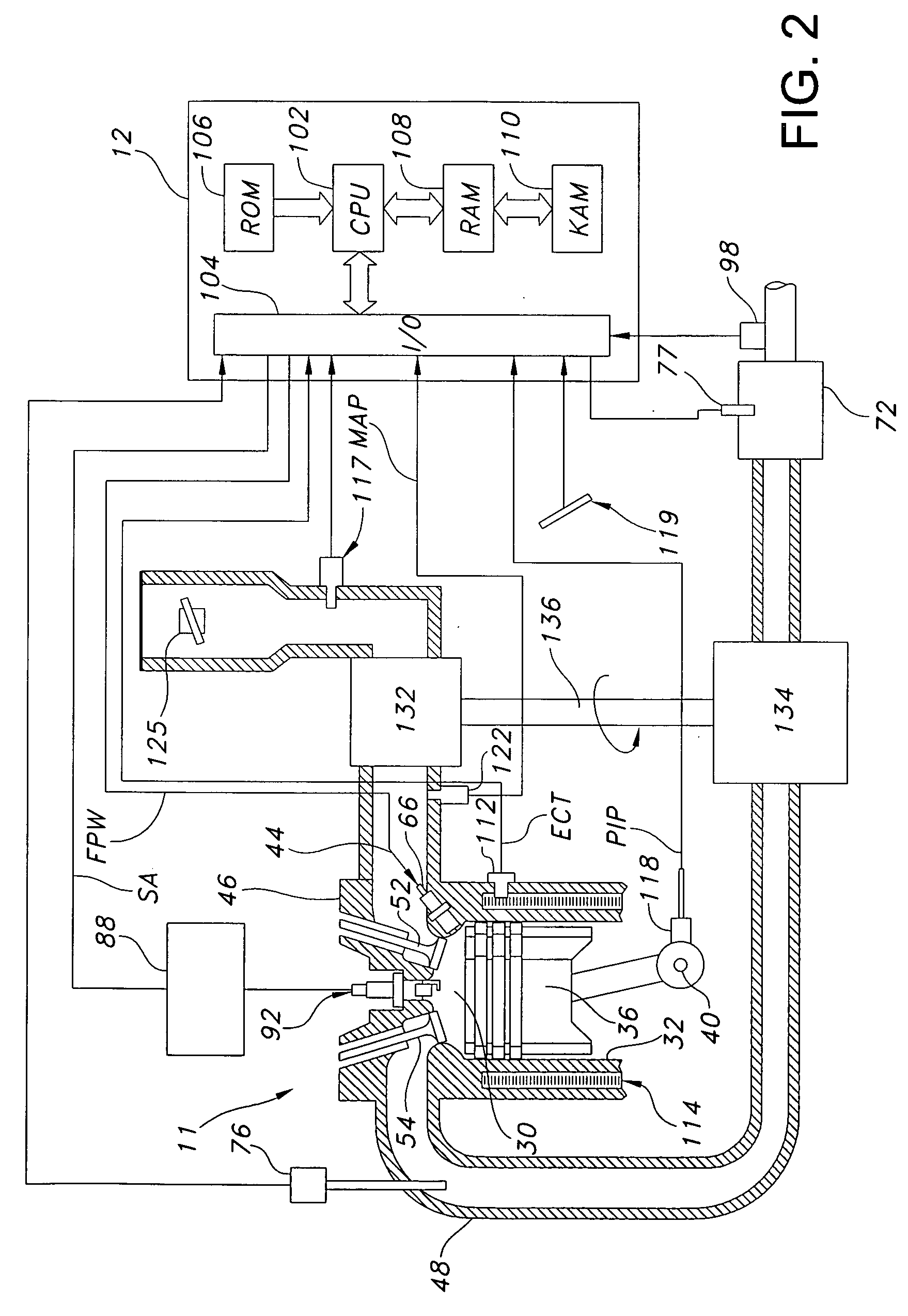
[0014] As noted above, the present application describes an approach that provides boost compensation to reduce effects of compressor delays, such as the phenomena known as turbo-lag, as well as improve various other engine operations, such as engine cold starting. In one particular example, a separate source of compressed air is available to be rapidly supplied to the engine (e.g., via the intake manifold, intake port, or cylinder head) during selected conditions, such as in response to a driver tip-in, thus reducing turbo-lag. The additional air from the air amplifier serves to provide a rapid increase in cylinder charge, even when manifold pressure has yet to be increased by a turbocharger. Furthermore, the injection of higher pressure air into the engine cylinders results in an almost immediate increase in exhaust flow, which enhances function of the turbocharger, and thus can further reduce the turbo-lag period. In other words, it is possible to create more flow into the cylind...


PUM


Abstract

A boost system for an engine, comprising an engine having at least a cylinder with an intake valve configured to cover and uncover an intake opening into the cylinder, the cylinder coupled to an intake manifold; a compression device coupled to said engine; and an air delivery nozzle configured to deliver pressurized air to said cylinder via said opening, where said nozzle has a converging-diverging shape so that discharged air is at a supersonic velocity at least under some operating conditions.

Description

BACKGROUND AND SUMMARY [0001] Engines may use boosting devices, such as turbochargers, to increase engine power density. Thus, under steady state operation, smaller displacement turbocharged engines can produce power equivalent to larger displacement engines. However, under dynamic driving conditions, the smaller turbocharged engine may have less transient performance than a larger, naturally aspirated engine. [0002] As one example, when a turbocharged engine is operating at low load, the turbocharger speed is low and intake manifold pressure is low. When the engine load is suddenly increased, there may be a lag before the turbocharger speed increases and intake manifold pressure rises. This delay may be referred to as “turbo-lag.” During this delay, the engine power or torque output may be less than the desired value, and less than the steady state available output. [0003] One approach that attempted to provide intake manifold pressure boost with minimal delay is described in SAE p...

Claims


Application Information

Patent Timeline
Patent Type & Authority Applications(United States)
IPC IPC(8): F02D23/00
CPCF01L3/06F02B29/02F02D21/10Y02T10/146Y02T10/12
Inventor BERGER, ALLEONE, THOMAS
Owner FORD GLOBAL TECH LLC
Why Eureka
Try Eureka