Leak inspection device

a technology of leak detection and leakage, which is applied in the direction of measurement devices, structural/machine measurement, instruments, etc., can solve the problems of deteriorating measurement sensitivity, affecting the accuracy of leak detection, so as to reduce the capacity of the vacuum pump and reduce the discharging time.

Inactive Publication Date: 2007-05-31
DENSO CORP
View PDF12 Cites 11 Cited by
  • Summary
  • Abstract
  • Description
  • Claims
  • Application Information

AI Technical Summary

Benefits of technology

[0008] The present invention has been accomplished to solve the above problems. A first object of the present invention is to provide a leak inspection device characterized in that a volume of redundant air to be discharged from the vacuum chamber is decreased so that the capacity of the vacuum pump can be reduced and the discharging time can be also reduced.
[0009] A second object of the present invention is to provide a leak inspection device characterized in that, when the space in the vacuum chamber is made smaller, dilution of the He gas which has leaked out from the product can be prevented so that the measuring sensitivity can be enhanced.
[0010] The present invention provides a leak inspection device comprising: a vacuum chamber 2 for accommodating an object 1 to be inspected; a vacuum pump 3 for discharging air from the vacuum chamber 2; a tracer gas supply source 4 for supplying and charging tracer gas into the object 1 to be inspected; and a leak detector 5 for detecting tracer gas which has leaked out from the object 1 to be detected, wherein the tracer gas is pressurized and charged into the object 1 to be inspected, which is accommodated in the vacuum chamber 2, so as to detect leakage of the tracer gas from the object 1 to be inspected, the gas leak inspection device further comprising a displacement change means (8, 8A to 8G, 9) for changing the volume of the vacuum chamber 2. Due to the foregoing, it is possible to reduce the volume of the exhaust gas discharged from the vacuum chamber 2 and it is also possible to decrease the capacity of the vacuum pump 3. As it is possible to reduce the size of the vacuum chamber 2, dilution of the He gas which has leaked out from the object to be inspected can be prevented. Accordingly, the measuring sensitivity can be enhanced.
[0013] In a leak inspection device of the present invention, the vacuum chamber 2 is cylindrical. Due to the above constitution, when a shape of the vacuum chamber is made to agree with the shape of the object 1 to be inspected, it becomes possible to further eliminate redundant space from the vacuum chamber 2.

Problems solved by technology

Further, it takes a long time to discharge the air from the vacuum chamber.
Also, when the volume of the vacuum chamber is large, the concentration of the He gas which has leaked out from the product is low in the vacuum chamber.
Accordingly, the measurement sensitivity is deteriorated.

Method used


Image

  • Leak inspection device
  • Leak inspection device
  • Leak inspection device

Examples


Embodiment Construction

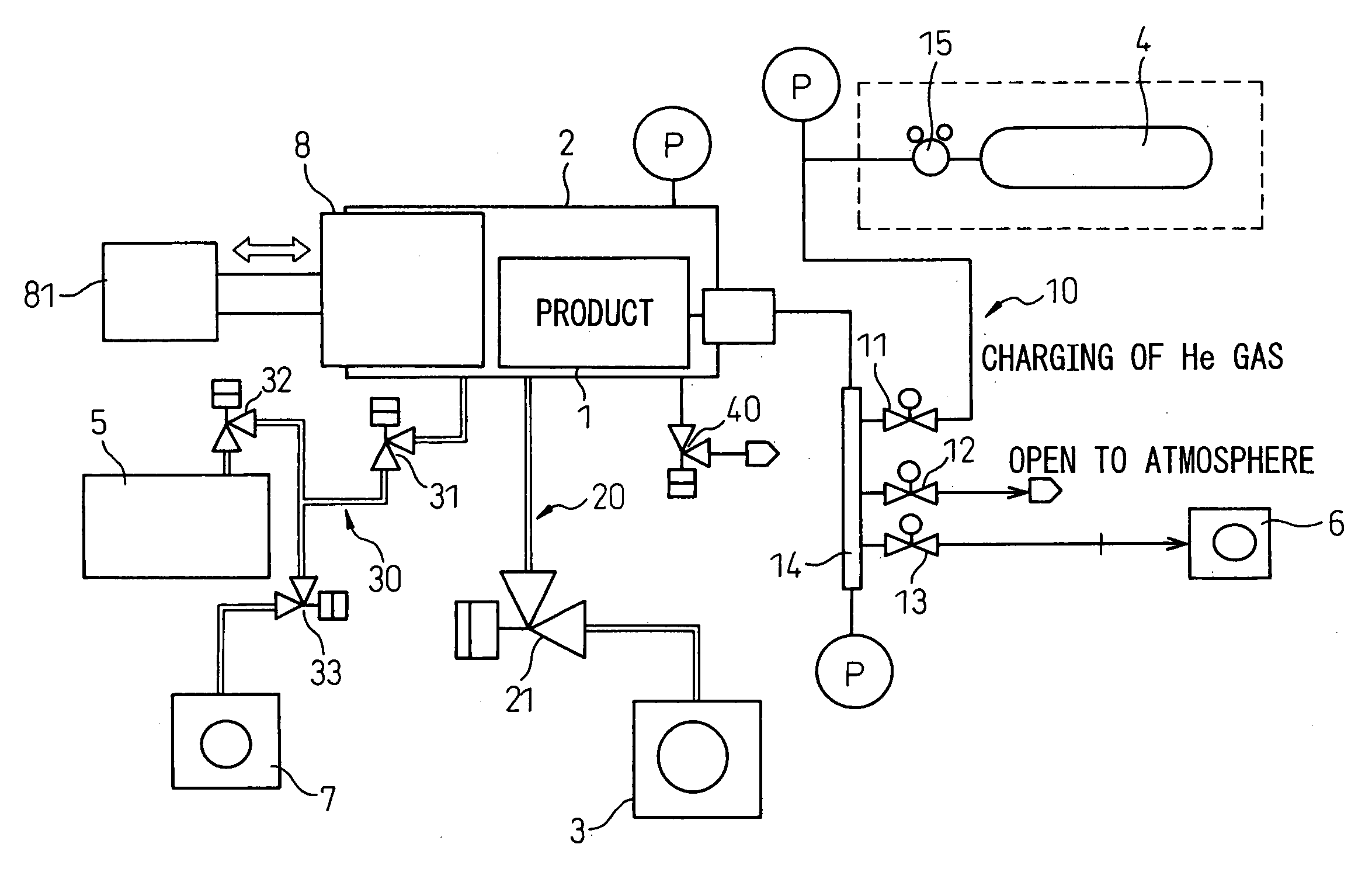
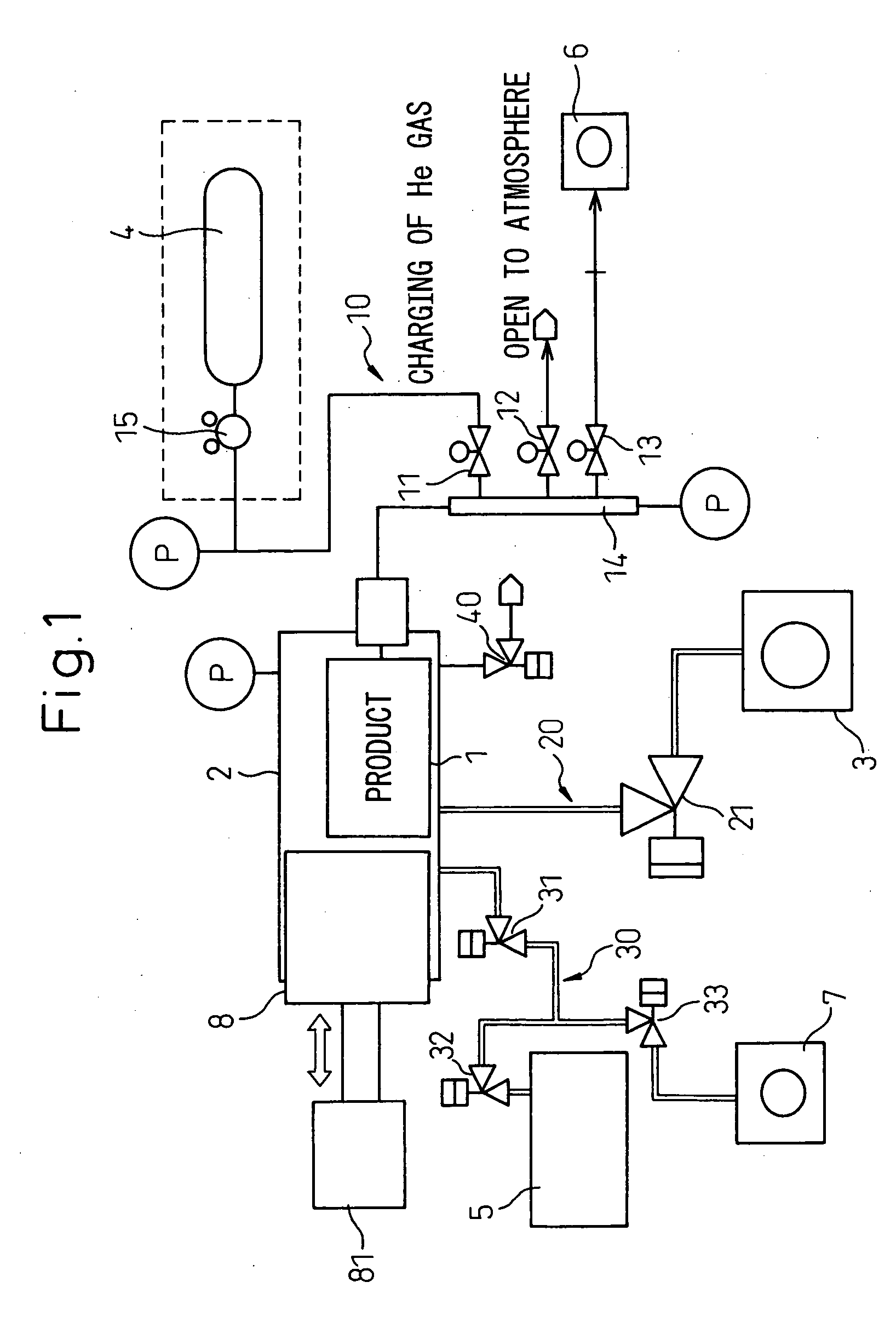
[0027] Referring to the drawings, a leak inspection device of an embodiment of the present invention will be explained below. FIG. 1 is an overall arrangement view of the leak inspection device of the embodiment of the present invention. The leak inspection device basically includes: a vacuum chamber 2 for accommodating a product 1 which is an object to be inspected; a vacuum pump 3 for discharging air from the vacuum chamber 2; a helium bomb (gas cylinder) (He bomb) 4, which is a tracer gas supply source, for supplying tracer gas such as helium gas (He gas) into the product 1; and a leak detector 5 for detecting He gas which has leaked out from the product 1.

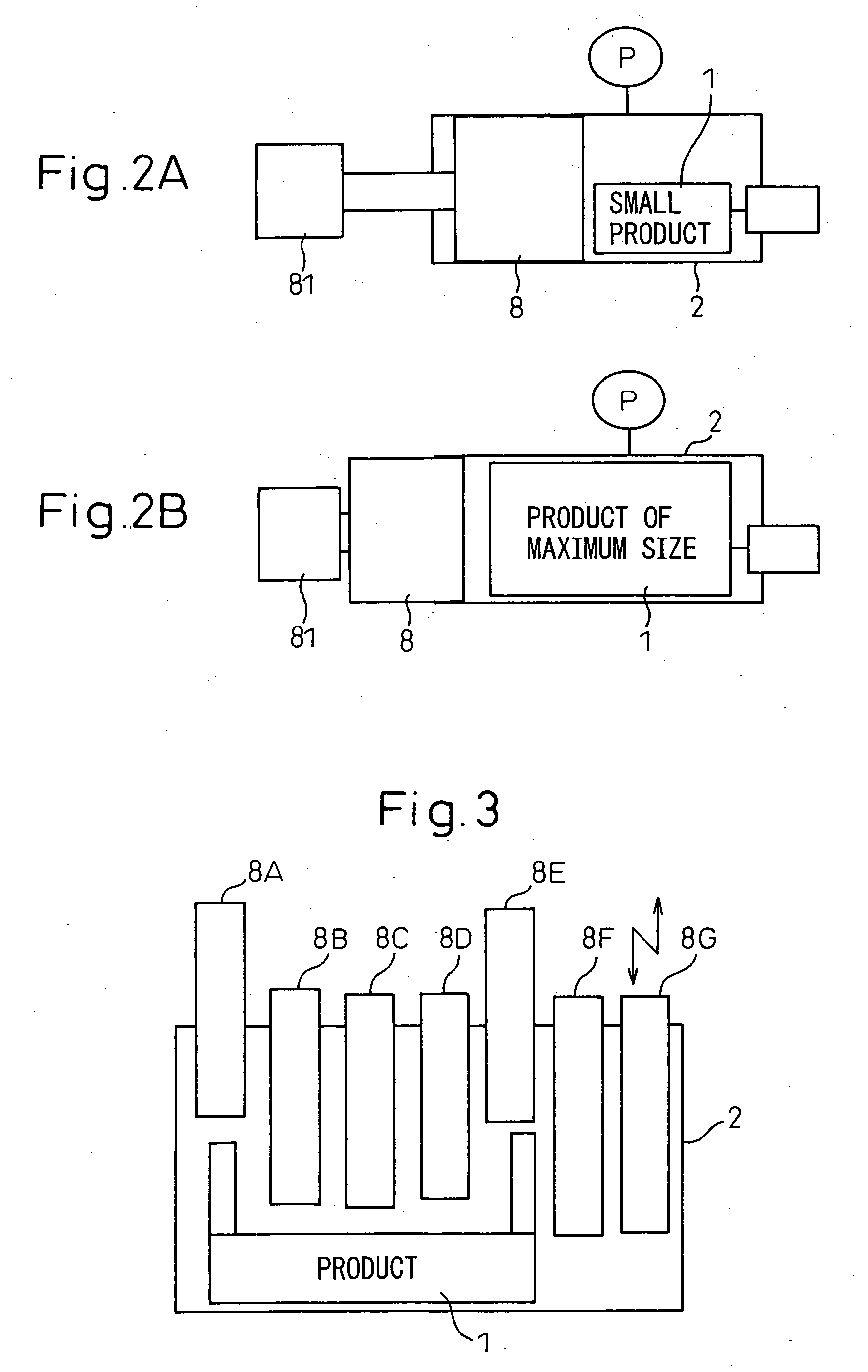
[0028] The vacuum chamber 2 has a capacity in which the product 1, the size of which is variously changed, can be accommodated. Further, the vacuum chamber 2 includes a displacement changing means by which a volume in the vacuum chamber 2 can be changed. This displacement changing means will be described in detail later. The v...


PUM


Abstract

In an inspection device in which a leakage of He gas from a product 1 is detected when He gas is pressurized and charged into the product 1 accommodated in a vacuum chamber 2, a variable displacement means, capable of changing the volume of the vacuum chamber corresponding to a size of the product 1, is provided in the vacuum chamber. An example of the variable displacement means is a variable displacement piston 8 which is arranged in the vacuum chamber and moves along wall faces of the vacuum chamber. A plurality of variable displacement pistons may be provided.

Description

BACKGROUND OF THE INVENTION [0001] 1. Field of the Invention [0002] The present invention relates to a leak inspection device in which air leakage from an object to be inspected is detected with a leakage inspection medium (tracer gas) such as helium gas (He gas). [0003] 2. Description of the Related Art [0004] Concerning prior art inspection methods to inspect a minute gas leak in an object to be inspected, an inspection method has been provided in which a helium gas leak detector, to detect helium gas which has leaked out from an object to be detected, is used. An example of this inspection method is a vacuum type helium gas leak inspection method in which the gas leak inspection device shown in FIG. 6 is used. [0005] In the vacuum type leak inspection device shown in FIG. 6, an inspection is conducted according to the inspection flow shown in FIG. 8, which will be described as follows. A product 1, which is an object to be inspected, is accommodated in a vacuum chamber 2, and a p...

Claims


Application Information

Patent Timeline
Patent Type & Authority Applications(United States)
IPC IPC(8): G01M3/20
CPCG01M3/229
Inventor KANEMATSU, YOSHIKUNITAKENAKA, HIROSHI
Owner DENSO CORP
Why Eureka
Try Eureka