

Stacked battery module and battery pack
a battery module and stacked technology, applied in secondary cell servicing/maintenance, sustainable manufacturing/processing, safety/protection circuit, etc., can solve the problems of unit battery whose impedance has risen or whose capacity has fallen, and can get into an overcharged state, threatening the stacked battery module,
- Summary
- Abstract
- Description
- Claims
- Application Information
AI Technical Summary
Benefits of technology
Problems solved by technology
Method used
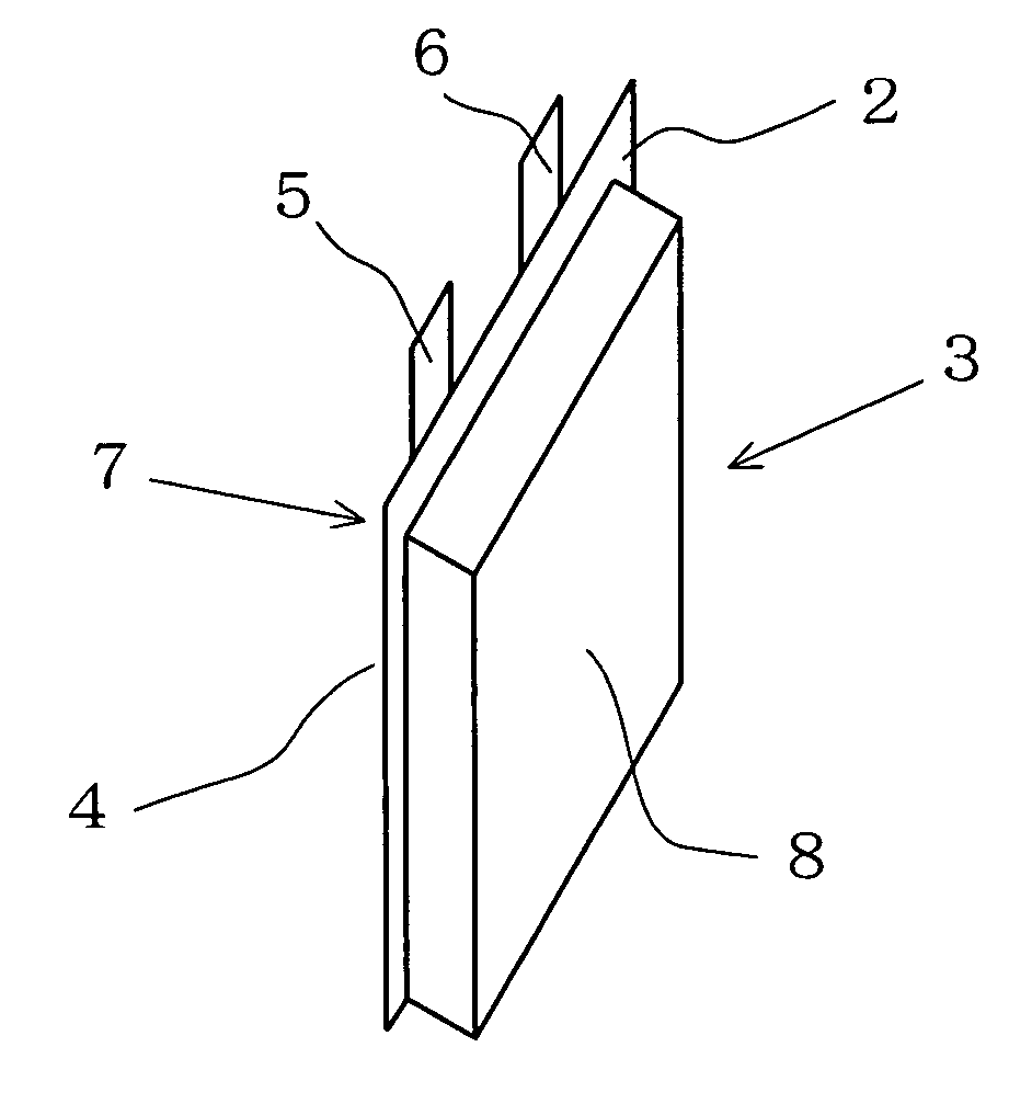
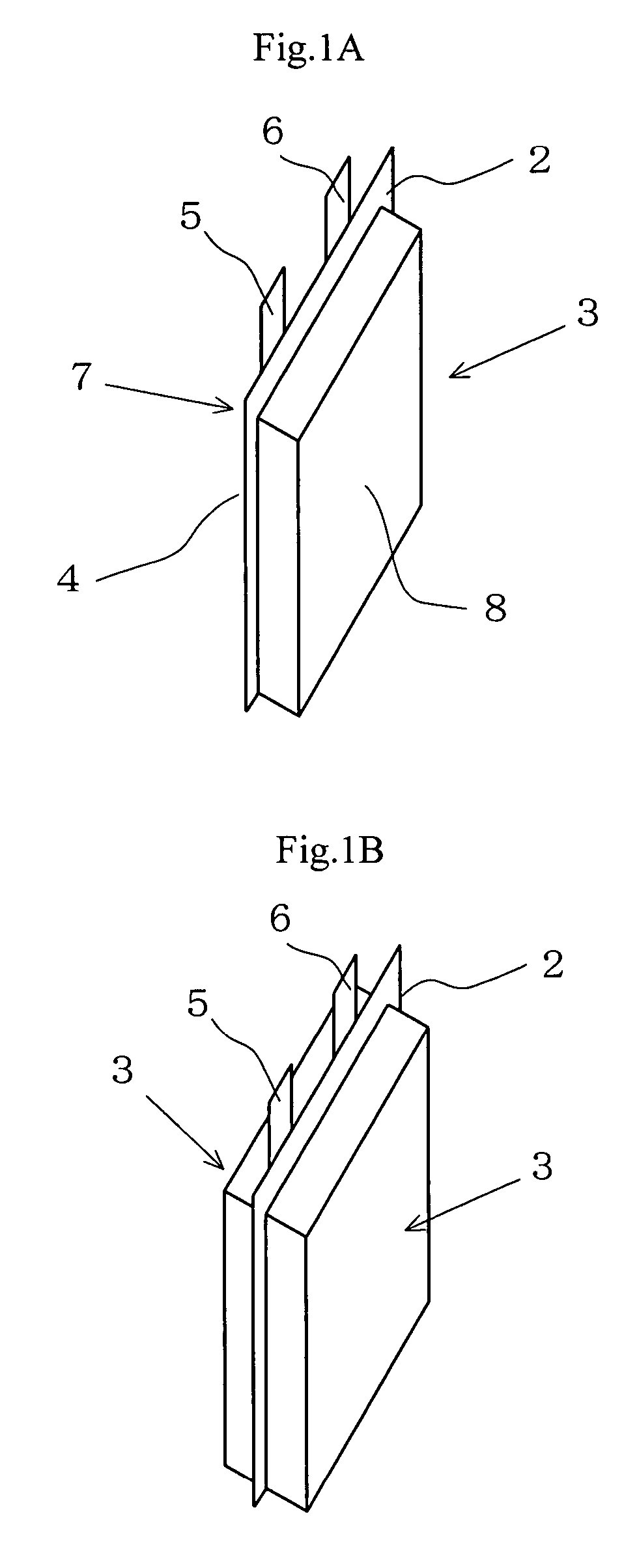
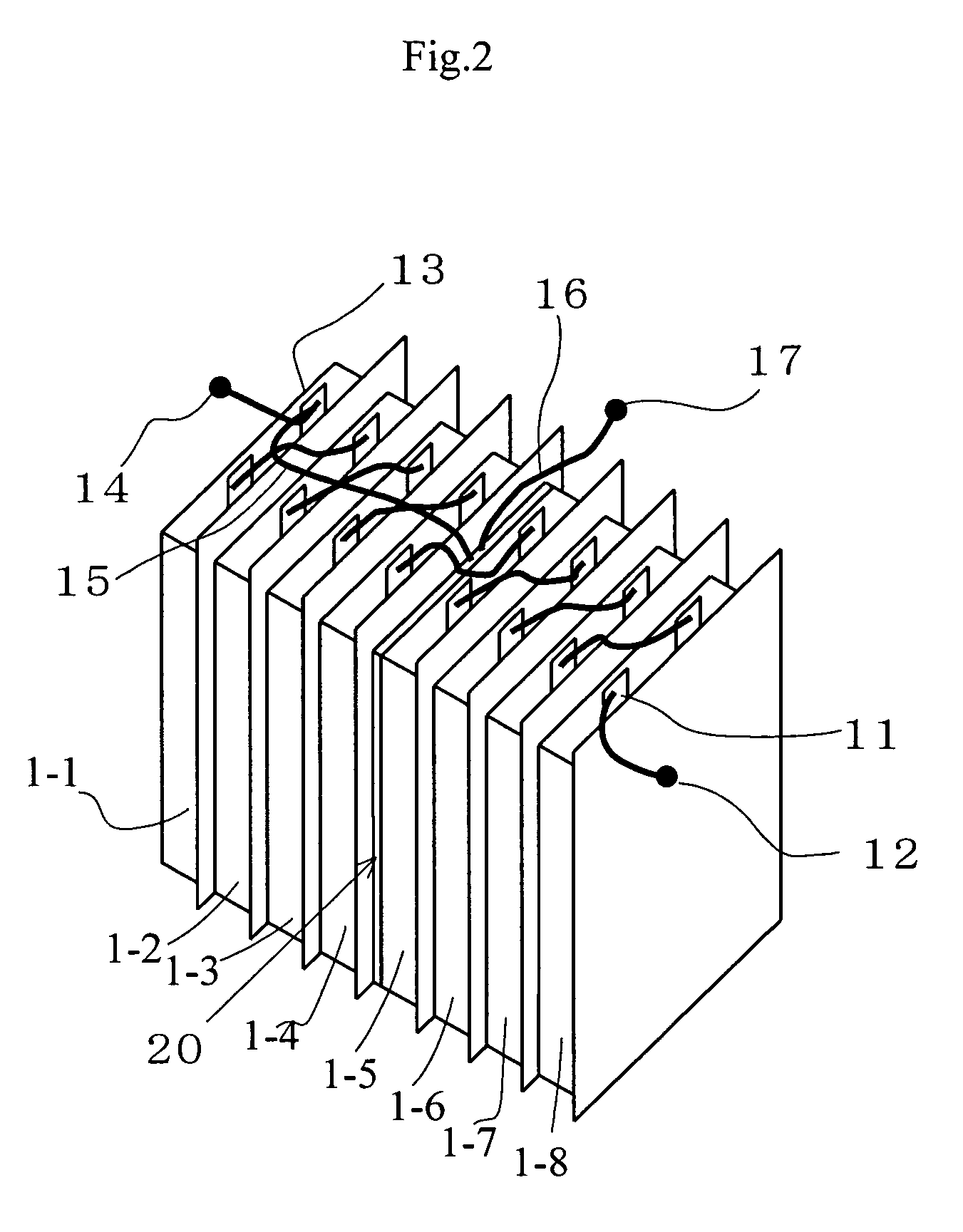
Image

Examples
example 1
Preparation of Unit Battery
[0104] Lithium-manganese oxide was used as positive active material and dry-mixed with an electric conductibility providing agent. The mixture was uniformly dispersed in N-methyl-2-pyrrolidone (NMP), to which PVDF had been dissolved as binder, to prepare slurry. The slurry was applied to the surface of a 20 μm-thick aluminum foil and the NMP was evaporated to produce a positive electrode sheet. The solid contents ratio in the positive electrode of lithium-manganese oxide:electric conductibility providing agent:PVDF was made equal to 90:6:4 by weight. The positive electrode sheet was punched to show a width of 55 mm and a height of 100 mm. The aluminum foil without applied slurry was punched to show a width of 10 mm and height of 15 mm as current taking out lead.
[0105] Graphite was selected as negative electrode material and uniformly dispersed in N-methyl-2-pyrrolidone (NMP), to which PVDF had been dissolved as binder, to prepare slurry. The slurry was ...
example 2
[0118] Unit batteries were prepared as in Example 1 except that polypropylene showing a melting temperature of 160° C. was used for the porous film separators and an overcharging test was conducted as in Example 1.
[0119] As a result, no abnormal heat generation was observed after the activation of the temperature fuse in the overcharging test.
example 3
[0120] Twelve unit batteries were prepared and connected in series as in Example 1 except that lithium manganese oxide and cobalt-doped lithium-nickel oxide expressed by composition formula of LiNi0.8Co0.2O2 were mixed by a mass ratio of 8:2 to form a positive electrode and an overcharging test was conducted as in Example 1.
[0121] As a result, no abnormal heat generation was observed after the activation of the temperature fuse in the overcharging test.
PUM
| Property | Measurement | Unit |
|---|---|---|
| melting temperature | aaaaa | aaaaa |
| temperature | aaaaa | aaaaa |
| discharging current | aaaaa | aaaaa |
Abstract
Description
Claims
Application Information