Multiple spot photomedical treatment using a laser indirect ophthalmoscope

a laser indirect ophthalmoscope and multi-spot technology, applied in the field of retinal tissue patterned photothermal treatment, can solve the problems of damage to the patient's sensory retina, irreversible damage to the overlying sensory retina, and s

Inactive Publication Date: 2007-05-31
TOPCON MEDICAL LASER SYST INC
View PDF42 Cites 152 Cited by
  • Summary
  • Abstract
  • Description
  • Claims
  • Application Information

AI Technical Summary

Problems solved by technology

While this type of laser light treatment slows the damage rate of the underlying disease, it has its set of problems.
For example, because the treatment entails exposing the eye to a large number of laser light pulses for a long period of time (typically each pulse is on the order of 100 ms), damage can be caused to the patient's sensory retina from the heat that is generated.
Although visible light is predominantly absorbed in the RPE, this type of treatment irreversibly damages the overlying sensory retina and negatively affects the patient's vision.
Specifically, certain parts of the eye are difficult to treat with this type of device.
However, this area is not completely accessible with a slit-lamp-delivered laser system.
Also, the slit-lamp-mounted laser delivery device is not well suited for treating small infants or bed-ridden patients.
Furthermore, it is difficult to orient the patient's head position with slit-lamp-mounted systems.
Thus, these devices have limited ability to treat patients with detached retinas and other conditions where gas or dense fluids have been introduced into the eye to secure detached tissues prior to laser exposure.
This is difficult and tiresome for both patient and physician.

Method used


Image

  • Multiple spot photomedical treatment using a laser indirect ophthalmoscope
  • Multiple spot photomedical treatment using a laser indirect ophthalmoscope
  • Multiple spot photomedical treatment using a laser indirect ophthalmoscope

Examples


first embodiment

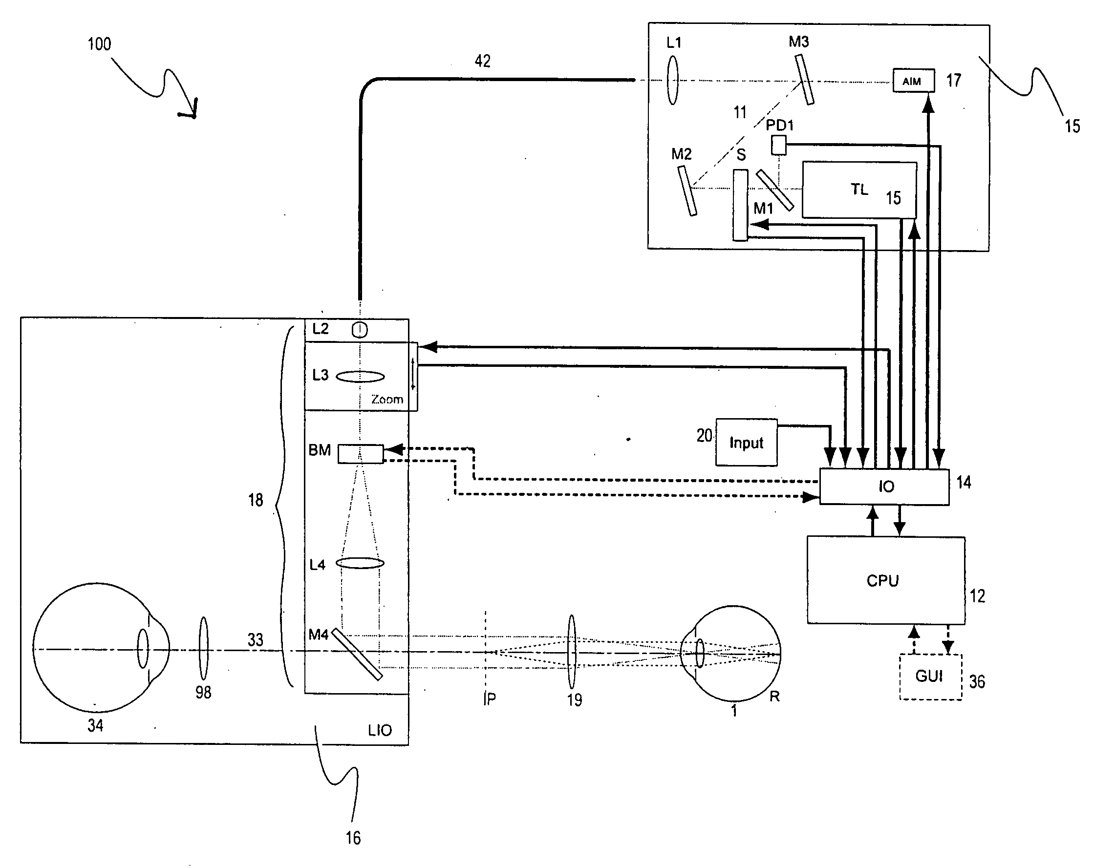
[0026]FIG. 3 is a schematic diagram of a photomedical system 100 in accordance with the invention. The photomedical system 100, which may be used for photomedical treatment or diagnosis, includes a CPU 12, an electronic input / output device 14, a light generation unit 15, and an LIO apparatus 16. The light generation unit 15 is optically coupled to the LIO apparatus 16 by a fiber unit 42. A user, such as a physician, wears the LIO apparatus 16 to view a target with his / her eye 34 through an ophthalmic lens 19. In this case, the target is the retina of an eye 1 (i.e., the patient's eye). The user 34 may see the eye 1 directly or through a screen, such as graphical user interface 36. The CPU 12 is coupled to the light generation unit 15 to control light generation. Optionally, the CPU 12 also controls the LIO apparatus 16. The CPU 12 may be a microprocessor, microcontroller, or any other type of suitable control electronics.

[0027] The light generation unit 15 includes a light source 10...

second embodiment

[0042]FIG. 6 is a schematic diagram of the beam multiplier BM. In this embodiment, the beam multiplier BM includes an optical element with focusing power, specifically an off-axis moving lens 68 that is movable transversely to the optical axis and able to rotate eccentrically (i.e. not about its optical axis). As the lens 68 spins, the optical beam 11 coming from the lens L2 reaches different parts of the lens 68, thus getting refracted differently depending on what portion of the lens 68 is encountered. The lens L4 directs the optical beam 11 coming from different angles emanating from lens 68 to different spots on the mirror M4. The lens 68 may be replaced with a mirror in other embodiments, where different portions of the moving lens 68 would reflect the beam at different angles.

third embodiment

[0043]FIG. 7 is a schematic diagram of the beam multiplier BM. In this embodiment, the beam multiplier BM includes a rotating reflective polygon scanner 70 and a reflective element 72. The rotating polygon 70 may be configured to provide different deviation angles on different facets. As the polygon rotates about an axis 71, the optical beam 11 coming from the lens L2 hits different points on the polygon 70 and leaves the polygon 70 at different angles. The reflective element 72 receives the optical beam 11 from the polygon 70 and directs it to the lens L4. The lens L4 forwards the optical beam 11 to the mirror M4. The position on the mirror M4 that the optical beam 11 strikes differs depending on which part of the polygon 70 reflects the optical beam 11.

[0044]FIGS. 8 and 9 are schematic diagrams of fourth and fifth embodiments of the beam multiplier BM, respectively. The fourth and fifth embodiments utilize diffraction elements. In FIG. 8, the beam multiplier BM includes a transmis...


PUM


Abstract

A laser indirect ophthalmoscope (LIO) apparatus for photomedical treatment and / or diagnosis is presented. The LIO apparatus allows multiple spot ophthalmic surgery to be performed in a wider range of patient positions and less intrusively than currently available methods. The LIO apparatus utilizes a separate or integral beam multiplier that generates one or more optical beams via spatial and / or temporal separation, and an optical system that conditions and directs the one or more optical beams to a target to form a pattern. The LIO apparatus includes a headset, and is therefore wearable by the user (e.g., a physician).

Description

CROSS REFERENCE TO RELATED APPLICATION(S) [0001] This application claims the benefit of priority under 35 U.S.C. §119(e) of U.S. Ser. No. 60 / 737,548, filed on Nov. 16, 2005, the entire content of which is incorporated herein by reference.FIELD OF THE INVENTION [0002] The present invention relates generally to patterned photothermal treatment of retinal tissue and particularly to such treatment using a laser indirect ophthalmoscope. BACKGROUND INFORMATION [0003] Conditions such as diabetic retinopathy and age-related macular degeneration are subject to photocoagulative treatment with laser light. While this type of laser light treatment slows the damage rate of the underlying disease, it has its set of problems. For example, because the treatment entails exposing the eye to a large number of laser light pulses for a long period of time (typically each pulse is on the order of 100 ms), damage can be caused to the patient's sensory retina from the heat that is generated. During the tre...

Claims


Application Information

Patent Timeline
Patent Type & Authority Applications(United States)
IPC IPC(8): A61B3/10A61B3/00A61B18/18A61N5/06
CPCA61B3/0008A61B3/12A61B2018/00916A61B2018/2025A61B2018/2205A61B2019/262A61F9/008A61F9/00821A61F9/00823A61F2009/00863A61F2009/00897A61N2005/0643A61B2090/502
Inventor ANDERSEN, DANMORDAUNT, DAVID
Owner TOPCON MEDICAL LASER SYST INC
Why Eureka
Try Eureka