Optical disk device

a technology of optical disk and optical disk, which is applied in the field of optical disk devices, can solve the problems of difficult calibration of the write pulse shape, inability to write data in good condition, and increased noise influen

Inactive Publication Date: 2007-05-31
HITACHI-LG DATA STORAGE +1
View PDF11 Cites 15 Cited by
  • Summary
  • Abstract
  • Description
  • Claims
  • Application Information

AI Technical Summary

Benefits of technology

[0041] It is clearly understood that the invention is capable of solving the problem (1) while satisfying the restrictive condition (2). This makes it possible to realize the optimization of the write pulse and power conditions within a short period of time with the simplified structure, thus providing the optical disk device that assures the readout conversion with the dri

Problems solved by technology

Meanwhile if the disk medium allows writing only once like the DVD-R, it is difficult to calibrate the write pulse shape.
When the signal written on the DVD is read by the single drive unit, the influence resulting from noise may become much greater.
As the aforementioned drive unit is not preliminarily provided with the optimum write pulse information with respe

Method used


Image

  • Optical disk device
  • Optical disk device
  • Optical disk device

Examples


first embodiment

Block Structure

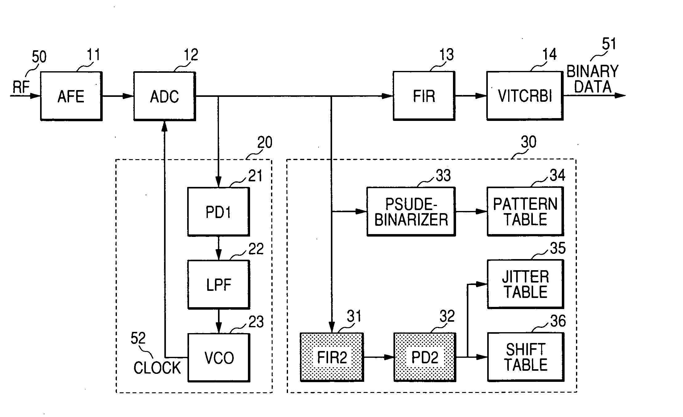
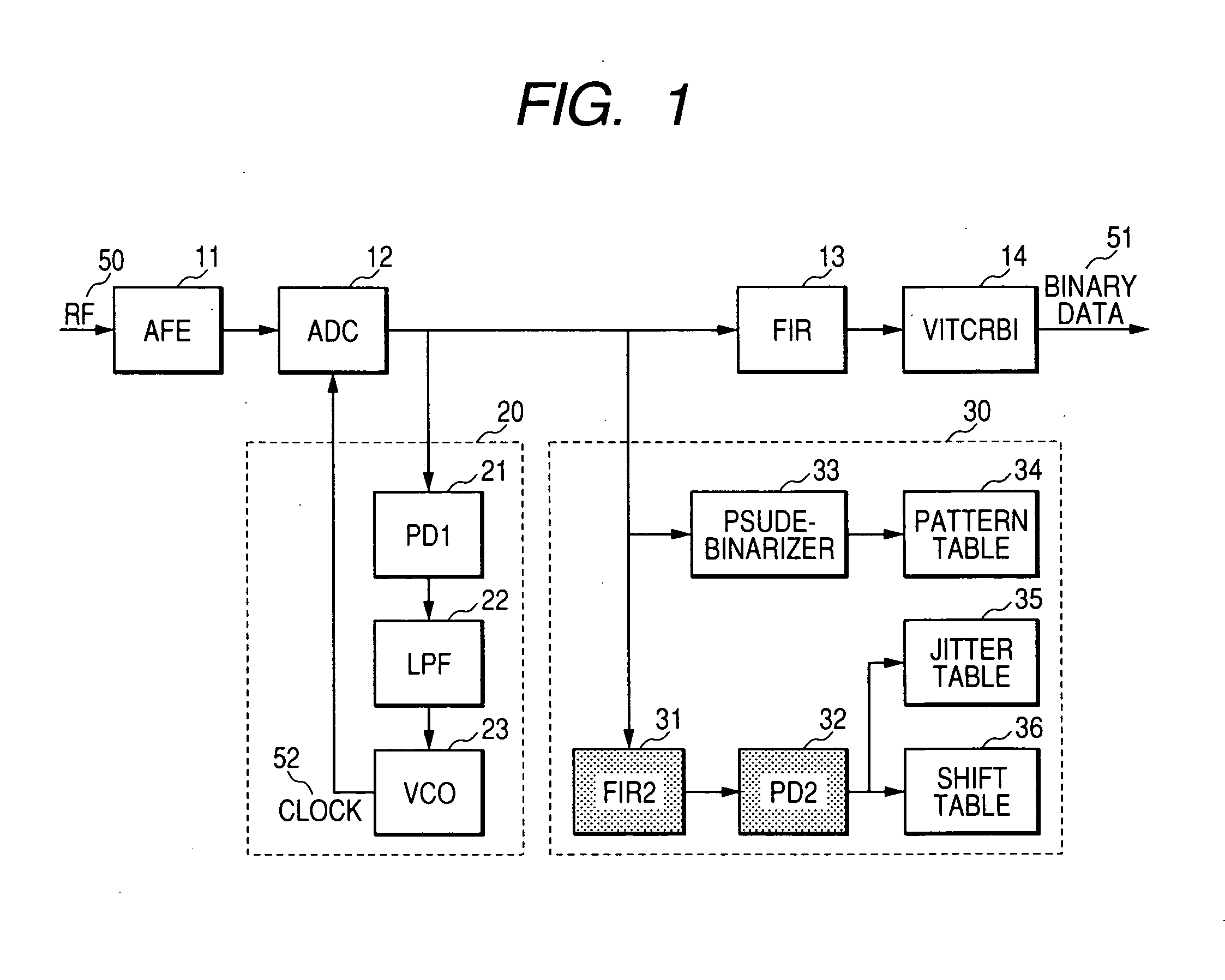
[0069]FIG. 9 shows a structure of a readout signal processing circuit for an optical disk device according to the present invention. The difference between the structure shown in FIG. 1 and the structure shown in FIG. 9 will be explained hereinafter.

(1) Shared FIR Filter

[0070] The circuit structure shown in FIG. 1 is provided with two FIR filters, that is, the FIR filter 13 for the Viterbi decoder 14, and the FIR filter 31 within the jitter detector circuit 30. It is well known that if the constraint length (class bit number) of the Viterbi decoder is even numbered, the tap number of the FIR filter 13 becomes even. As the trial writing is not performed simultaneously with the normal write / read operation, the tap coefficient of the FIR filter 13 may be changed to function as the FIR filter 31. It is preferable to change the tap coefficient of the FIR filter 13 to widen the variable range of the boost amount. Assuming that the tap number is set to 4, it is preferab...

second embodiment

Trial Writing Sequence

[0072] The write strategies for the respective DVD media will be described prior to the explanation of the embodiment of the trial writing sequence according to the present invention.

[0073]FIGS. 10 and 11 graphically show the write strategies for the respective media of DVD-R, DVD-RW, and DVD-RAM. FIG. 10 shows the normal speed write condition, and FIG. 11 shows the high-speed write condition, respectively. The write strategy suitable in accordance with the write physics of the respective media is employed. The write physics inherent to each medium will not be described in detail as it is beyond the essential points of the present invention. However, it should be known to optimize the write strategy.

[0074] Besides the jitter detection realized in the present invention, asymmetry value, value β, and modulation degree will be measured in the following sequence. Each of those values is well known as the evaluation index. They may be easily obtained through cal...

third embodiment

Optical Disk Device

[0100]FIG. 25 is a view of an embodiment that shows a structure of an optical disk device according to the present invention. An optical disk medium 100 is rotated by a motor 160. Upon readout, a laser power / pulse controller 120 controls electricity applied to a laser diode 112 within an optical head 110 to generate a laser beam such that the light intensity reaches the level commanded by the CPU 140. The laser beam 114 is collected by an objective lens 111 to form an optical spot 101 on the optical disk medium 100. The reflecting light 115 from the optical spot 101 is detected by a photo-detector 113 via the objective lens 111. The photo-detector is formed of a plurality of divided optical detection elements. A readout signal processor 130 readouts the information written on the optical disk medium 100 using the signal detected by the optical head 110. Upon writing, the laser power / pulse controller 120 converts predetermined write data into a predetermined writ...


PUM


Abstract

A write type optical disk device with the PRML mode allows accuracy in the trial writing to be improved accompanied with the high speed processing while assuring the readout compatibility. A readout signal that has been A/D converted at timing that interposes the edge has its phase compensated with the even numbered FIR filter. The level at the edge point and the absolute values thereof are accumulated respectively so as to provide a circuit for detecting the edge shift and jitter. Coping with the high speed processing, the edge shift of the readout signal is detected at the position where the edge shift is around zero, thus improving the accuracy in learning of trial writing.

Description

CLAIM OF PRIORITY [0001] The present application claims priority from Japanese application JP 2005-339615 filed on Nov. 25, 2005, the content of which is hereby incorporated by reference into this application. FIELD OF THE INVENTION [0002] The present invention relates to an optical disk device that generates a write mark exhibiting a physical property different from that of other portion on a recording medium to write information data thereon. BACKGROUND OF THE INVENTION [0003] The use of optical disk media, for example, a DVD-RAM and a DVD-RW made of a rewritable phase-change optical write material has been widely distributed. Recently a high-capacity Blu-ray Disc conforming to a recording of a high-vision broadcasting program has been commercialized using blue laser. Commercialization of the optical disk device which allows a single drive unit to write and read the information not only on the DVD but also on the Blu-ray disk is further demanded. In the case where the information ...

Claims


Application Information

Patent Timeline
IPC IPC(8): G11B7/00
CPCG11B20/10009G11B20/10037G11B20/10055G11B20/10296G11B20/10481G11B20/1816G11B7/00456G11B7/005G11B7/0062G11B7/1267
Inventor MINEMURA, HIROYUKI
Owner HITACHI-LG DATA STORAGE
Why Eureka
Try Eureka