Check patentability & draft patents in minutes with Patsnap Eureka AI!

Method and apparatus for managing flow control in PCI express transaction layer

Inactive Publication Date: 2007-05-31
AVAGO TECH INT SALES PTE LTD
View PDF8 Cites 44 Cited by
  • Summary
  • Abstract
  • Description
  • Claims
  • Application Information

AI Technical Summary

Benefits of technology

[0008] The invention generally pertains to a method and apparatus wherein a central Credit Controller Entity (CCE) is connected to a PCIE fabric environment by means of several buses. Flow Control information sent to the CCE over two of the buses indicates the buffer storage capacity that is available at respective Receiver components in the PCIE fabric. The CCE processes the Flow Control information, to generate updates that are sent by a third bus to Transmitter components corresponding to the Receivers. In one useful embodiment, directed to a method of Flow Control management, the CCE provides a repository adapted to store credit count information that represents the available storage capacity of respective Receivers. Embodiments of the invention thus provide a centralized entity, to significantly enhance flexibility in managing Flow Control updates generated by a PCIE root complex or end point. It is anticipated that these embodiments will enable a user to selectively maximize throughput or RAM buffering output, or to minimize latency. The method further comprises routing further credit count information from a given Receiver to the CCE, for storage in the repository, following each of successive events that affect the storage capacity of the given Receiver. The CCE is operated to selectively process the credit count information stored in the repository, in order to generate an update credit count. The update credit count is then selectively sent to a given Transmitter, to enable the given Transmitter to send a transmission to the given Receiver. Embodiments of the invention thus provide a centralized entity, to significantly enhance flexibility in managing Flow Control updates generated by a PCIE root complex or end point. It is anticipated that these embodiments will tend to maximize throughput and RAM buffering output, and to minimize latency.

Problems solved by technology

If the intended Receiver does not have enough credits to receive the TLP, the Transmitter must block the transmission of the TLP, possibly stalling other TLPs that are using the same virtual channel.

Method used


Image

  • Method and apparatus for managing flow control in PCI express transaction layer
  • Method and apparatus for managing flow control in PCI express transaction layer
  • Method and apparatus for managing flow control in PCI express transaction layer

Examples


Embodiment Construction

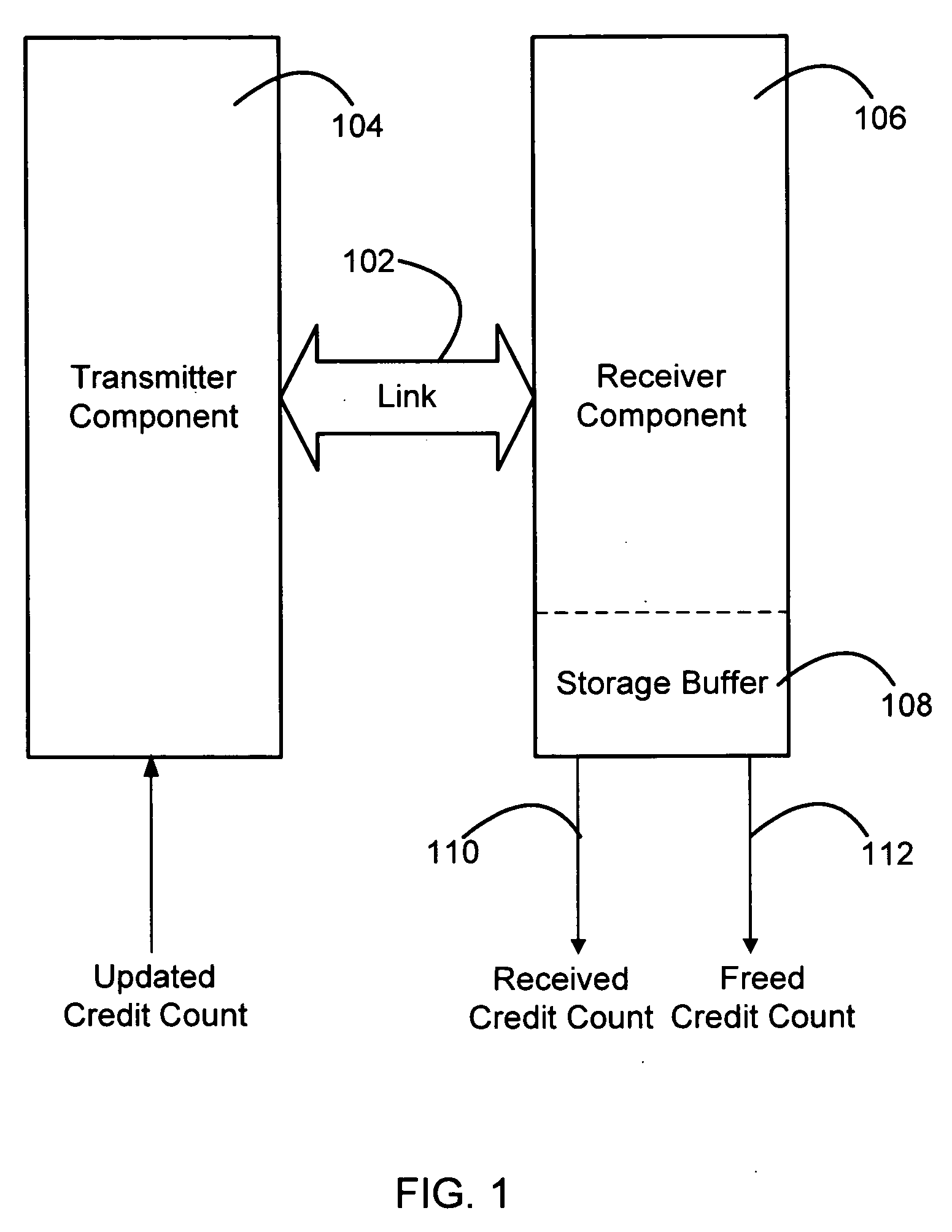
[0014] A PCI-Express (PCIE) fabric is composed of point-to-point links that interconnect a set of components. As an illustration, FIG. 1 shows a PCIE Link 102 between fabric components 104 and 106. In its most general form, a PCIE Link represents a dual-simplex communication channel between two components, and consists of two low voltage differential signal pairs, a transmit pair and a receive pair. However, for purposes of illustration, FIG. 1 shows component 104 designated to be a Transmitter component, and component 106 designated to be a Receiver component. It is to be understood that in some applications the roles of components 104 and 106 would be reversed. FIG. 1 further shows Receiver 106 provided with a storage buffer 108. While not shown, component 104 could have a similar storage buffer.

[0015] PCIE uses packets to communicate information between components. Packets are formed in the Transaction and Data Link Layers, to carry information from the transmitting component to...


PUM


Abstract

A method and apparatus is provided wherein a central Credit Controller Entity (CCE) is connected to a PCIE fabric environment by means of several buses. Flow Control information sent to the CCE over two of the buses indicates the buffer storage capacity that is available at respective Receiver components in the PCIE fabric. The CCE processes the Flow Control information, to generate updates that are sent by a third bus to Transmitter components corresponding to the Receivers. In one useful embodiment, directed to a method of Flow Control management, the CCE provides a repository adapted to store credit count information that represents the available storage capacity of respective Receivers. The method further comprises routing further credit count information from a given Receiver to the CCE, for storage in the repository, following each of successive events that affect the storage capacity of the given Receiver. The CCE is operated to selectively process the credit count information stored in the repository, in order to generate an update credit count. The update credit count is then selectively sent to a given Transmitter, to enable the given Transmitter to send a transmission to the given Receiver.

Description

BACKGROUND OF THE INVENTION [0001] 1. Technical Field [0002] The invention disclosed and claimed herein generally pertains to a method for managing flow control updates in a PCI Express (PCIE) environment. More particularly, the invention pertains to a method of the above type wherein a Credit Control Entity (CCE) receives credit count information that represents available storage capacity of receivers in the PCIE environment. Even more particularly, the invention pertains to a method of the above type wherein updates, derived by the CCE from the credit count information, are used to enable transmissions to the receivers. [0003] 2. Description of the Related Art [0004] In a PCIE fabric environment, packet traffic is directed to virtual channels (VCs) by mapping packets with traffic class labels to corresponding VCs. Moreover, PCIE provides the capability of mapping multiple traffic classes onto a single VC. This is achieved by arranging for traffic flowing through a VC to be multipl...

Claims


Application Information

Patent Timeline
IPC IPC(8): G06F11/00G01R31/08H04L1/00H04L12/26
CPCG06F13/4027
Inventor BRETI, JEFFREY WILLIAMSANDERS, DOUGLAS ELLIOTTBHARADWAJ, HARISHBEHERA, SUPARNABOYD, GORDON DOUGLASBOMBARD, RICHARD JOHNHERMAN, PHILIP WALDRON JR.
Owner AVAGO TECH INT SALES PTE LTD
Features
  • R&D
  • Intellectual Property
  • Life Sciences
  • Materials
  • Tech Scout
  • Unparalleled Data Quality
  • Higher Quality Content
  • 60% Fewer Hallucinations
Learn More