Fiber optical transmission system, transmitter and receiver for DQPSK modulated signals and method for stabilizing the same

a fiber optic transmission system and optical signal technology, applied in the field of fiber optic transmission systems, can solve the problems of difficult generation of dqpsk modulated signals, complex generation and reception of dqpsk signals, and complex transmission curves, and achieve the effect of simple and cost-effectiv

Active Publication Date: 2007-05-31
RPX CORP
View PDF16 Cites 46 Cited by
  • Summary
  • Abstract
  • Description
  • Claims
  • Application Information

AI Technical Summary

Benefits of technology

[0028] It is a first object of the invention to provide a DQPSK transmitter of the above-mentioned kind stabilizing the Mach-...

Problems solved by technology

However, the generation and reception of DQPSK signals is quite complex, as several feedback signals have to be generated to stabilize the transmitter and receiver, respectively.
Therefore, for generating a DQPSK signal, a binary bit stream has to be divided into two sequences corresponding to the in-phase and quadrature-phase components, respectively, such that the generation of a DQPSK modulated signal is more difficult compared to classical modulation schemes as e.g. On-Off Keying (OOK).
However, if the bias voltage is not adjusted properly, a bias deviation ΔV may occur, leading to a shift of the transmission curve such that the maximum optical transmission is no longer attained for +/−VπV but for a higher voltage, as is the case for the dashed c...

Method used


Image

  • Fiber optical transmission system, transmitter and receiver for DQPSK modulated signals and method for stabilizing the same
  • Fiber optical transmission system, transmitter and receiver for DQPSK modulated signals and method for stabilizing the same
  • Fiber optical transmission system, transmitter and receiver for DQPSK modulated signals and method for stabilizing the same

Examples


Embodiment Construction

[0056] The following detailed description of the invention refers to the accompanying drawing. The same reference numerals may be used in different figures of the drawing to identify the same or similar elements.

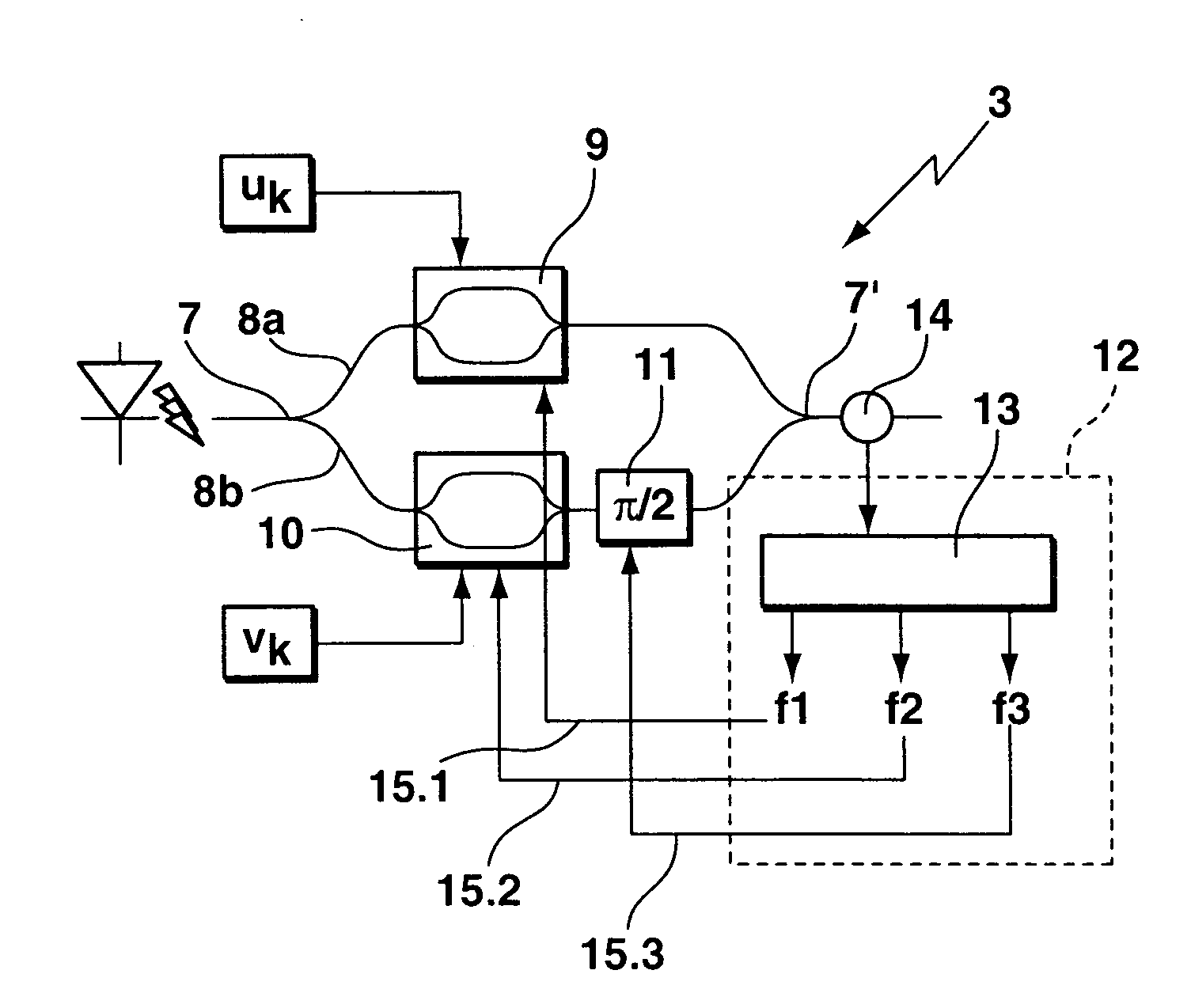
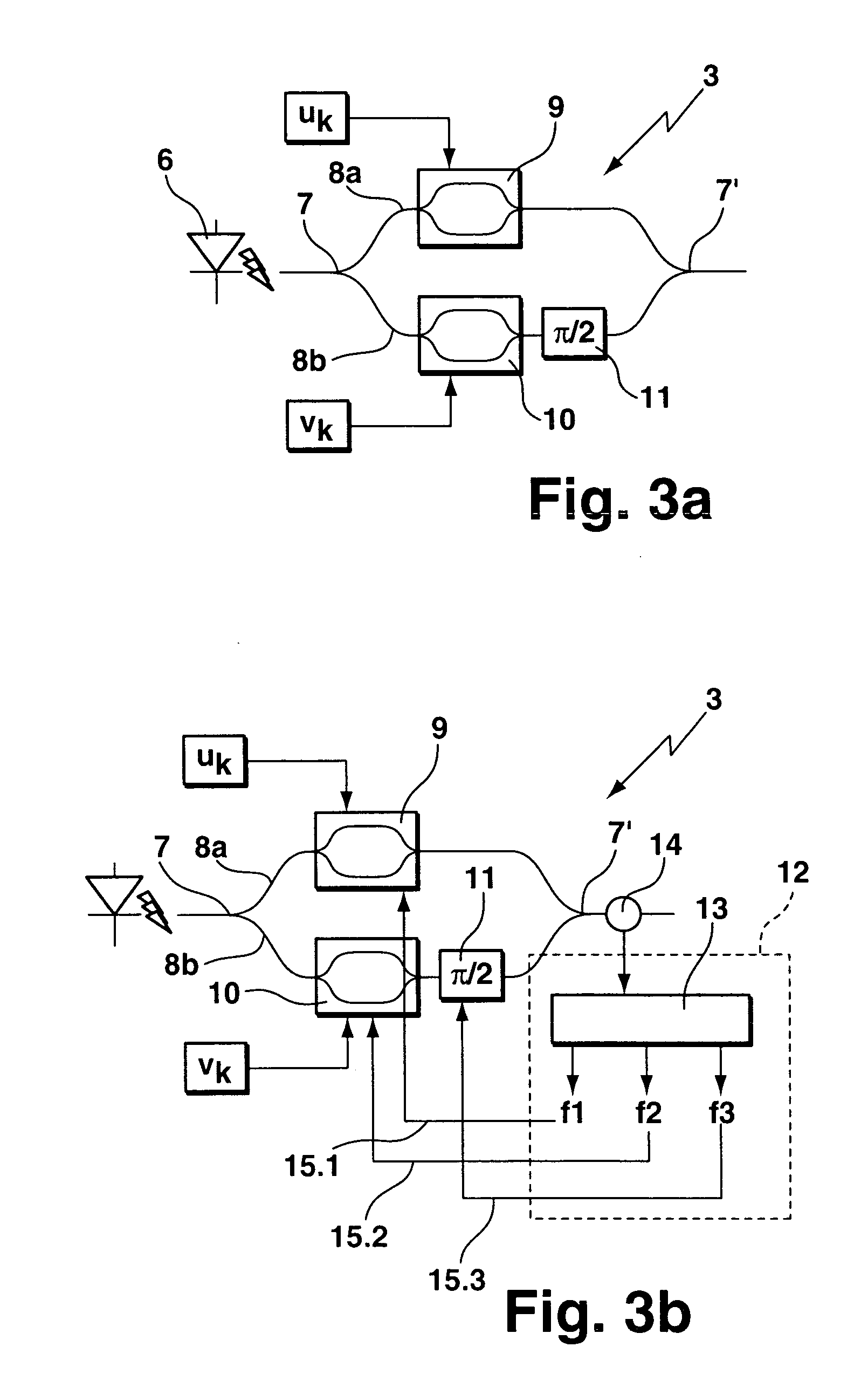
[0057] In the following, the stabilization of the DQPSK transmitter 3 represented in FIG. 3a will be explained. For the stabilization of the Mach-Zehnder modulators 9, 10 and the π / 2 phase shifter 11 of the transmitter 3, it comprises a feedback circuit 12 shown in FIG. 3b. A sample signal is extracted from the output of the transmitter 3 after the combiner 7′ by a tap coupler 14. The sample signal is fed to the feedback circuit 12 which comprises a photodiode 13 for o / e-conversion of the sample signal. The feedback circuit 12 uses the sample signal for generating three bias signals 15.1 to 15.3 each being modulated with a different pre-defined frequency f1 to f3, which are provided to the Mach-Zehnder modulators 9, 10 and the π / 2 phase shifter 11, respectively. The bias si...


PUM


Abstract

A transmitter (3) for generating a DQPSK-modulated optical signal, comprising: a splitter (7) for dividing an optical carrier signal into a first and second branch (8a, 8b), a first and second Mach-Zehnder interferometer (9, 10) in the first and second branch (8a, 8b), respectively, a phase shifter (11) in one of the branches (8b) generating a nominal phase shift of π/2, and a combiner (7′) for combining the optical output signals of the two branches (8a, 8b). The transmitter (3) has a feedback circuit (12) generating at least a first and second bias signal (15.1 to 15.3) for adjusting a bias of at least the first and second Mach-Zehnder interferometers (9, 10), the feedback circuit (12) comprising: a detector for generating at least a first and second feedback signal from a sample signal extracted from the optical signal after the combiner (7′), and for each bias signal: a local oscillator generating an auxiliary signal modulating the bias signal (15.1 to 15.3) at a pre-defined frequency (f1, f2, f3), a lock-in detector determining a phase difference between the feedback signal and the auxiliary signal, and a bias circuit for generating the bias signal (15.1 to 15.3) from an output signal of the lock-in detector, wherein the pre-defined frequencies of the auxiliary signals (f1, f2, f3) are different from one another (f1≠f2≠f3) and preferably no integer multiples of each other.

Description

[0001] The invention is based on a priority application EP 05 292 532.8 which is hereby incorporated by reference. TECHNICAL FIELD [0002] The invention relates to a transmitter for generating a DQPSK-modulated optical signal comprising: a splitter for dividing an optical carrier signal into a first and second branch, a first and second Mach-Zehnder interferometer in the first and second branch, respectively, each being operated with an electrical modulation signal, a phase shifter in one of the branches generating a nominal phase shift of π / 2, and a combiner for combining the optical output signals of the two branches. [0003] The invention also relates to a receiver for demodulating a DQPSK-modulated optical signal, comprising: a splitter for dividing the optical signal into a first and second branch, each of the branches comprising: a balanced receiver following a differential interferometer, each of the differential interferometers comprising: a time delay and a phase shifter arra...

Claims


Application Information

Patent Timeline
IPC IPC(8): H04B10/04H04B10/50H04B10/556H04B10/66
CPCG02F1/0123H04B10/505H04B10/5053H04B10/50575H04B10/50577H04B10/5561H04B10/66
Inventor CHARLET, GABRIELFAUCONNIER, THIBAUT
Owner RPX CORP
Why Eureka
Try Eureka