Supercritical refrigeration cycle

Inactive Publication Date: 2007-06-07
DENSO CORP
View PDF3 Cites 58 Cited by
  • Summary
  • Abstract
  • Description
  • Claims
  • Application Information

AI Technical Summary

Benefits of technology

[0017] In this aspect of the invention, as long as the temperature difference (ΔT) is not less than the predetermined value, the air capacity of the cooling fan (2a) is increased so that the actual radiation state of the refrigerant at the outlet of the radiator (2) is made to approach the ideal radiation state, thereby reducing the high pressure of the cycle to reduce the power consumption of the compressor (1).
[0018] In the case where the temperature difference (ΔT) is less than the predetermined value, on the other hand, the actual radiation state of t

Problems solved by technology

In the case where the operation of controlling the cooling fan of the high-pressure radiator in the subcritical refrigeration cycle, i.e. the operation of controlling the air capacity of the cooling fan, corresponding to the high pressure, is used as it is for the supercritical refrigeratio

Method used


Image

  • Supercritical refrigeration cycle
  • Supercritical refrigeration cycle
  • Supercritical refrigeration cycle

Examples


first embodiment

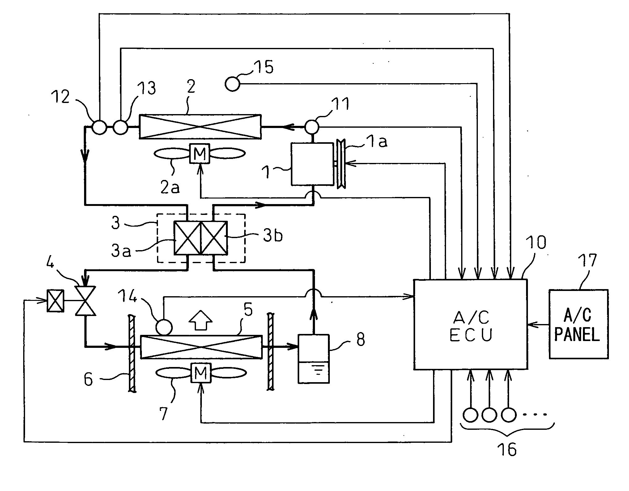
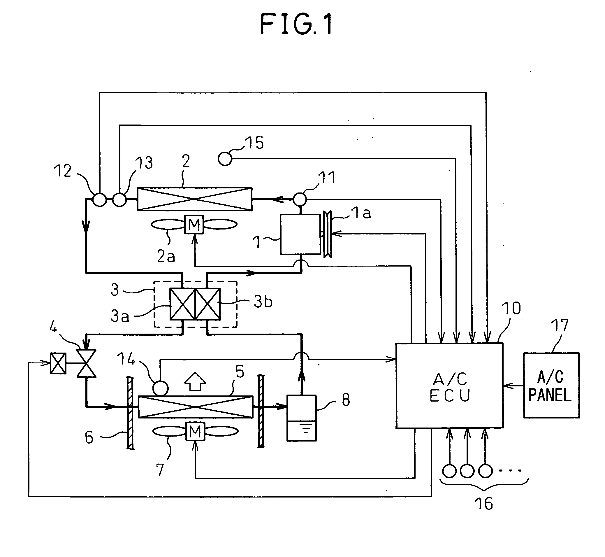
[0034]FIG. 1 is a diagram showing a configuration of the refrigeration cycle for an automotive air conditioning system according to a first embodiment of the invention. This refrigeration cycle uses CO2 as a refrigerant with the high pressure exceeding the critical pressure (supercritical state). This refrigeration cycle, therefore, constitutes a supercritical refrigeration cycle.

[0035] A compressor 1 for sucking in and compressing the refrigerant is either a fixed displacement refrigerant compressor or a variable displacement refrigerant compressor rotationally driven through an electromagnetic clutch 1a by the engine of an automotive vehicle not shown. The compressor 1 may be configured of an electrically-operated compressor.

[0036] A high-pressure radiator 2 generally called a gas cooler is arranged at the outlet of the compressor 1. This radiator 2 cools the refrigerant by exchanging heat between the discharged high-temperature high-pressure refrigerant in a supercritical state...

second embodiment

[0073] The first embodiment represents a case in which the cooling fan 2a of the radiator shown in FIG. 3 is always controlled without determining whether the cycle operation is in a supercritical state or a subcritical state. According to the second embodiment, on the other hand, as shown in FIG. 6, it is determined whether the cycle operation is in a supercritical state or a subcritical state as shown in FIG. 6 and, based on this determination, the control operation of the cooling fan 2a of the radiator is switched.

[0074]FIG. 6 is a flowchart showing the operation of controlling the cooling fan 2a of the radiator according to the second embodiment. Steps S1 to S5 are identical to those of FIG. 3. According to the second embodiment, step S6 of FIG. 6 determines in step S6 whether the actual high pressure Ph detected by the pressure sensor 12 is higher than the critical pressure of the CO2 refrigerant or not.

[0075] In the case where the actual high pressure Ph is higher than the c...


PUM


Abstract

A supercritical refrigeration cycle comprises a radiator 2 for cooling the refrigerant discharged from a compressor 1, a cooling fan 2a for blowing the atmospheric air to the radiator 2, a decompression unit 4 for decompressing the refrigerant at the outlet of the radiator 2 and having the opening degree thereof controlled to achieve a target high pressure, and an evaporator 5 for evaporating the low-pressure refrigerant decompressed by the decompression unit 4. The high pressure exceeds the critical pressure of the refrigerant. A value of information representing the difference between the actual radiation state of the refrigerant at the outlet of the radiator 2 and the ideal radiation state determined by the atmospheric temperature is calculated, and based on this value of information, the air capacity of the cooling fan 2a is controlled to decrease the difference. Thus, the cooling fan of the high-pressure radiator can be properly controlled in the supercritical refrigeration cycle.

Description

BACKGROUND OF THE INVENTION [0001] 1. Field of the Invention [0002] This invention relates to the operation of controlling the cooling fan of a high-pressure radiator in a supercritical refrigeration cycle that uses CO2 (carbon dioxide), of which the high pressure increases beyond the critical pressure (supercritical state), as a refrigerant. [0003] 2. Description of the Related Art [0004] In the supercritical refrigeration cycle using CO2 as the refrigerant, as indicated by thick solid line in FIG. 2, the pressure at the outlet of the high-pressure radiator assuming the maximum value of the coefficient of performance (COP) is known to change with the refrigerant temperature at the outlet of the high-pressure radiator. [0005] In view of this, it is known that the refrigerant temperature at the outlet of the high-pressure radiator is detected and, based on this refrigerant temperature at the outlet of the high-pressure radiator, the pressure at the outlet of the high-pressure radiato...

Claims


Application Information

Patent Timeline
IPC IPC(8): F25B39/04F25D17/04
CPCB60H1/3217B60H2001/325B60H2001/326B60H2001/3266B60H2001/3277B60H2001/3291F25B9/008F25B40/00F25B2309/061F25B2500/19F25B2600/11F25B2600/111F25B2600/17F25B2700/19F25B2700/2102F25B2700/2106F25B2700/21173
Inventor ISHIKAWA, HIROSHITSUBOKO, TOSHIO
Owner DENSO CORP
Why Eureka
Try Eureka