System and method for employing infrared illumination for machine vision

a machine vision and infrared illumination technology, applied in the field of machine vision systems, can solve the problems of washout of bright areas, high difficulty in reading etched or scribed symbols on wafers, and only a little more visible background areas

Inactive Publication Date: 2007-06-07
COGNEX TECH & INVESTMENT
View PDF25 Cites 14 Cited by
  • Summary
  • Abstract
  • Description
  • Claims
  • Application Information

AI Technical Summary

Problems solved by technology

The reading of etched or scribed symbology on a wafer can be highly problematic.
Thus, a simple increase in overall device contrast settings will result mainly in a washout of bright areas while making the dark background areas only somewhat more-discernable from adjacent scribes.
However, this solution still experiences some of the effects of contrast variation across a variably layered area of interest.
More significantly, many circuit fabrication processes specifically forbid the use of blue light in inspection because of the risk of inadvertent photoresist exposure.

Method used


Image

  • System and method for employing infrared illumination for machine vision
  • System and method for employing infrared illumination for machine vision
  • System and method for employing infrared illumination for machine vision

Examples


Embodiment Construction

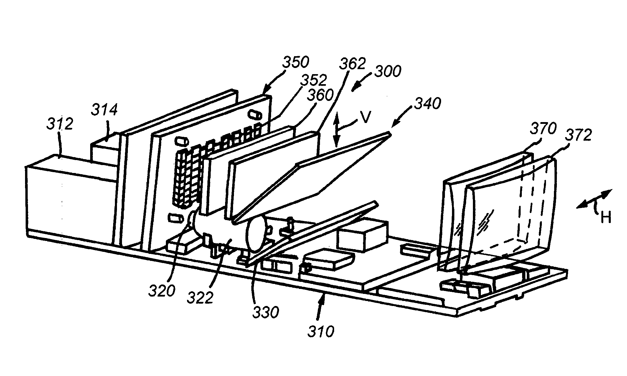
[0031]FIG. 3 details the internal components of a machine vision device 300 according to an illustrative embodiment of this invention. The device 300 consists of a main circuit board 310 that includes various power supply, image processing, networking and data storage hardware and software that can be implemented in accordance with conventional techniques. The board includes a power connection 312 and network interface 314. The network interface allows data transmission between the device and a computer or other data processing apparatus when desired. In this manner, identified wafers can be logged in a remote storage and processing device as appropriate. In addition, various device parameters can be programmed via the interface 314, which can interconnect with a computer running software that allows adjustment of device parameters. These parameters may include illumination control, imager settings (e.g. shutter speed, contrast, etc.), focus, and other wafer-identification-specific ...


PUM


Abstract

This invention provides a machine vision device adapted to read inscribed symbology on the surface of an object, such as a wafer, covered in photoresist that employs both bright field and dark field illumination in the infrared region. Using illumination with light in this spectral band, an inscribed symbol can be read by a camera sensor substantially unaffected by the presence of and / or number of layers of photoresist covering the symbol. The camera sensor is tuned to receive such illumination, and is thereby provided with an image that distinguishes the symbol's scribe lines on the underlying wafer surface from the surrounding specular wafer surface. The device includes a housing that supports the imager and imager lens below an array of IR LEDs. The sensor has an optical axis that is reflected from horizontal to vertical by a mirror and then back to horizontal by a beam splitter that is aligned with two spherical lenses and an outlet window at the front of the housing. The array is located in line with lenticular arrays behind the beam splitter, along the central optical axis of the lenses and window.

Description

BACKGROUND OF THE INVENTION [0001] 1. Field of the Invention [0002] This invention relates to machine vision systems and more particular to machine vision systems employed to read symbology located on substrates covered with a photoresist material. [0003] 2. Background Information [0004] Machine vision systems use image acquisition devices that include camera sensors to deliver information on a viewed subject. The system then interprets this information according to a variety of algorithms to perform a programmed decision-making and / or identification function. For an image to be most-effectively acquired by a sensor in the visible, and near-visible light range, the subject should be properly illuminated. [0005] In the example of symbology reading (also commonly termed “barcode” scanning) using an image sensor, proper illumination is highly desirable. Symbology reading entails the aiming of an image acquisition sensor (CMOS camera, CCD, etc.) at a location on an object that contains ...

Claims


Application Information

Patent Timeline
Patent Type & Authority Applications(United States)
IPC IPC(8): G06K7/10G06V10/145
CPCG06K9/2036G06V10/145
Inventor JAKOBOSKI, TIMOTHY A.LOONEY, BRIAN
Owner COGNEX TECH & INVESTMENT
Why Eureka
Try Eureka