Permanent magnet rotating machine
a permanent magnet, rotating machine technology, applied in dynamo-electric machines, magnetic circuit shapes/forms/construction, electrical apparatus, etc., can solve the problems of increasing the loss of copper in the stator winding, deteriorating the efficiency of the motor, and generating noise and vibration. , to achieve the effect of reducing noise and vibration and improving efficiency
- Summary
- Abstract
- Description
- Claims
- Application Information
AI Technical Summary
Benefits of technology
Problems solved by technology
Method used
Image
Examples
first embodiment
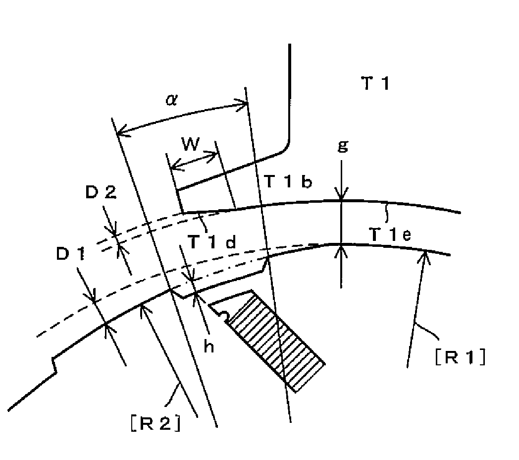
[0090] Next, the construction of the permanent magnet motor 30 of the first embodiment will be explained in further detail with reference to FIGS. 3 and 4. FIG. 3 is a cross section of the permanent magnet motor 30 as viewed from the direction perpendicular to the axial direction. FIG. 4 is an enlarged view of an essential part of FIG. 3.
[0091] In this embodiment, the rotor 50 having four poles (two pairs of poles) is used. In other embodiments in this invention which will be described below, rotors having four poles (two pairs of poles) are also used.
[0092] In the rotor 50, main magnetic poles and auxiliary magnetic poles alternate in the circumferential direction when viewed in cross section (perpendicular to the axial direction). Magnet insert holes are provided in the main magnetic poles.
[0093] In the following description, the main magnetic poles are represented by main magnetic poles [A] to [D] and the auxiliary magnetic poles are represented by auxiliary magnetic poles [AB...
second embodiment
[0164] A rotor 150 of a second embodiment shown in FIG. 13 is different from the rotor 50 of the first embodiment in that spaces (non-magnetic regions) are provided between outer end walls of the magnet insert holes and recesses.
[0165] In a main magnetic pole 150A of the rotor 150 of the second embodiment, magnet insert holes 151a1, 151a3 are arranged in V-shape as viewed from the center O of the rotor 150. Permanent magnets 152a1, 152a2 having a rectangular cross section are inserted into the magnet insert holes 151a1, 151a3.
[0166] In the second embodiment, the permanent magnets 152a1, 152a2 are inserted into the magnet insert holes 151a1, 151a3 such that no spaces are formed between the permanent magnets 152a1, 152a2 and outer end walls 151a2, 151a4 of the magnet insert holes 151a1, 151a3. Spaces (non-magnetic regions) 151a5, 151a6 are provided between the outer end walls 151a2, 151a4 of the magnet insert holes 151a1, 151a3 and second outer circumferential surface portions 150da...
third embodiment
[0168] A rotor 250 of a third embodiment shown in FIG. 14 is different from the rotor 50 of the first embodiment in the shapes of the magnet insert holes and the permanent magnets.
[0169] In a main magnetic pole 250A of the rotor 250 of the third embodiment, a magnet insert hole 251a1 having a circular arc cross section is provided. The circular arc shape is formed to bulge toward the center of the rotor. A permanent magnet 252a having generally the same cross section as the magnet insert hole 251a1 is inserted into the magnet insert hole 251a1.
[0170] In the rotor 250 of this embodiment, no spaces are provided between the permanent magnet 252a and second outer circumferential surface portions 250da, 250ab (the bottoms of recesses 250a1, 250a2).
PUM
 Abstract
Description
Claims
Application Information
 - R&D
- Intellectual Property
- Life Sciences
- Materials
- Tech Scout
- Unparalleled Data Quality
- Higher Quality Content
- 60% Fewer Hallucinations
Browse by: Latest US Patents, China's latest patents, Technical Efficacy Thesaurus, Application Domain, Technology Topic, Popular Technical Reports.
© 2025 PatSnap. All rights reserved.Legal|Privacy policy|Modern Slavery Act Transparency Statement|Sitemap|About US| Contact US: help@patsnap.com


