

Double-row self-aligning roller bearing and device for supporting wind turbine generator main shaft
a self-aligning, roller bearing technology, applied in the direction of liquid fuel engines, vessel construction, marine propulsion, etc., can solve the problems of excessive leeway, excessive labor and risks, and damage to the surface and frictional wear of the bearing assembly used to support the main shaft of the blade rotor, so as to increase the substantial bearing life
- Summary
- Abstract
- Description
- Claims
- Application Information
AI Technical Summary
Benefits of technology
Problems solved by technology
Method used
Image

Examples
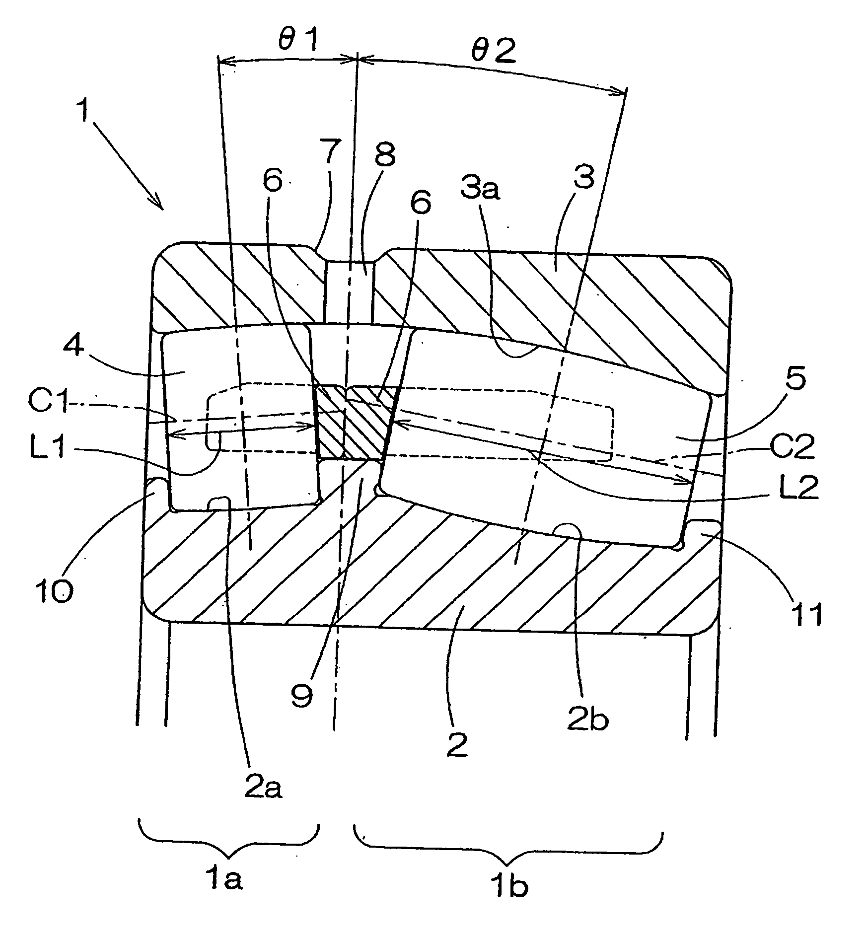
first embodiment
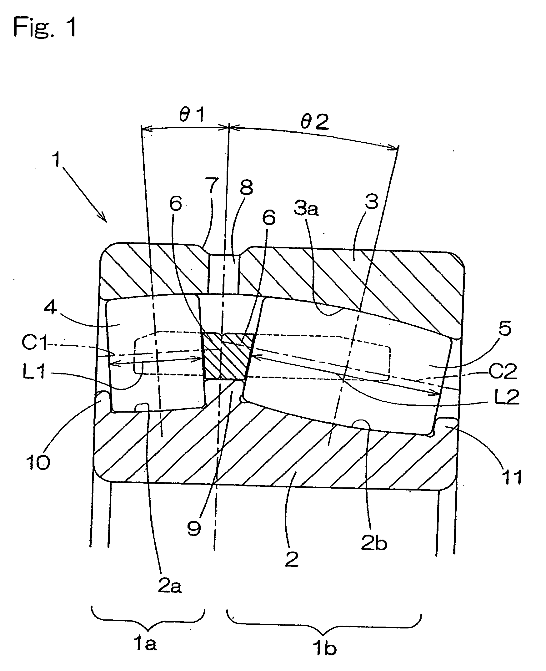
[0069]FIG. 2 illustrates a second preferred embodiment of the present invention. The double-row self-aligning roller bearing 1A shown therein is similar to the double-row self-aligning roller bearing 1 shown in and described with reference to FIG. 1 in connection with the first embodiment, except that as best shown therein the outer race 3 is divided into two split outer races 3A and 3B that are axially lined up. The split outer races 3A and 3B are so disposed as to form a gap d therebetween when held in a natural condition, that is, in a condition in which they have corresponding spherical raceway surfaces 3Aa and 3Ba occupying respective portions of the same spherical shape. While this double-row self-aligning roller bearing 1A is installed inside a bearing housing 20, the split outer races 3A and 3B are axially fastened together by the effect of a preload applied by a preload applying member 21 so as to reduce the gap d between the split outer races 3A and 3B. The preload applyin...
second embodiment
[0072] It is to be noted that the double-row self-aligning roller bearing of the structure can be modified as shown by 1B in FIG. 3. Specifically, the double-row self-aligning roller bearing 1B shown in FIG. 3 is modified in such a way that in addition to the splitting of the outer race 3, the inner race 2 is also divided into two split inner races 2A and 2B that are axially lined up. If the inner race 2 is so divided as described above, the inner race having left and right portions that are asymmetrical relative to each other can be manufactured easily.
[0073]FIG. 4 illustrates a third preferred embodiment of the present invention. The double-row self-aligning roller bearing 1C shown in FIG. 4 is of a type, in which the roller row 4 makes use of axially hollowed rollers each having an axially extending hollow 4b defined therein. In this example, the left and right roller rows 4 and 5 have the respective contact angles θ1 and θ2, which are the same and make use of the rollers 4 and ...
third embodiment
[0074] In the case of the third embodiment, since the rollers 4 of the left roller row are employed in the form of an axially hollowed roller, the amount of material used to form the rollers 4 can be reduced. Also, even though the load acting on the row of the rollers 4 is small, the slippage of the rollers 4 can be lessened because the weight of each roller 4 is reduced, and hence the frictional wear and surface damage can be alleviated.
[0075] A fourth preferred embodiment of the present invention will now be described with particular reference to FIGS. 5 and 6. The self-aligning roller bearing assembly 1D is a double-row self-aligning roller bearing, which is, in its entirety, divided into split bearing portions 1DA and 1DB that accommodate the left and right rows of the rollers 4 and 4, respectively, and that employ different elements associated with the load or the life, respectively.
[0076] This self-aligning roller bearing assembly 1D is a double-row self-aligning roller beari...
PUM
 Abstract
Description
Claims
Application Information