Optical fiber clamping assembly

a technology of optical fibers and clamping parts, applied in the field of optical fiber clamping parts, can solve the problems of difficult if not impossible insertion of fibers, and achieve the effects of enhancing the alignment of fibers, reducing insertion loss, and maintaining platform stability

Active Publication Date: 2007-06-07
COMMSCOPE TECH LLC
View PDF17 Cites 37 Cited by
  • Summary
  • Abstract
  • Description
  • Claims
  • Application Information

AI Technical Summary

Benefits of technology

[0011] The present invention overcomes the problems of prior art crimp-type connectors by providing for a clamping assembly having a sturdy substrate on which the fiber is clamped and held securely in alignment before, during, and after actuation of the clamping assembly. Specifically, rather than having the fiber clamped between two radially actuateable members, as in the prior art, the clamping assembly of the present invention uses just a single radially-moving member to clamp the fib...

Problems solved by technology

Since the channel is defined in a stationary platform, it is not subject to movement and variations in position prior to actuation which can make fiber insertion difficult if not impossible.
Again, the ability of the...

Method used


Image

  • Optical fiber clamping assembly
  • Optical fiber clamping assembly
  • Optical fiber clamping assembly

Examples


Embodiment Construction

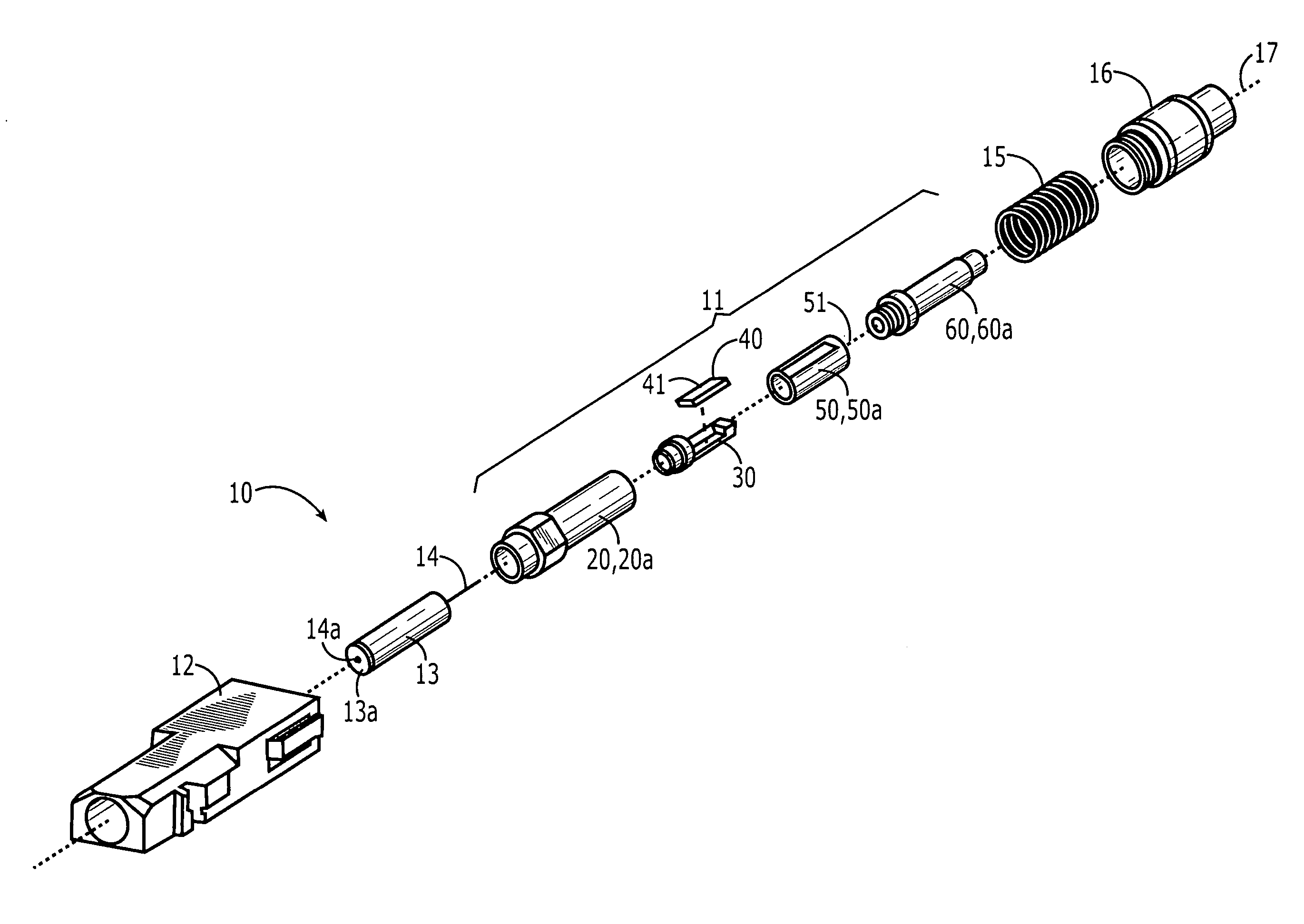
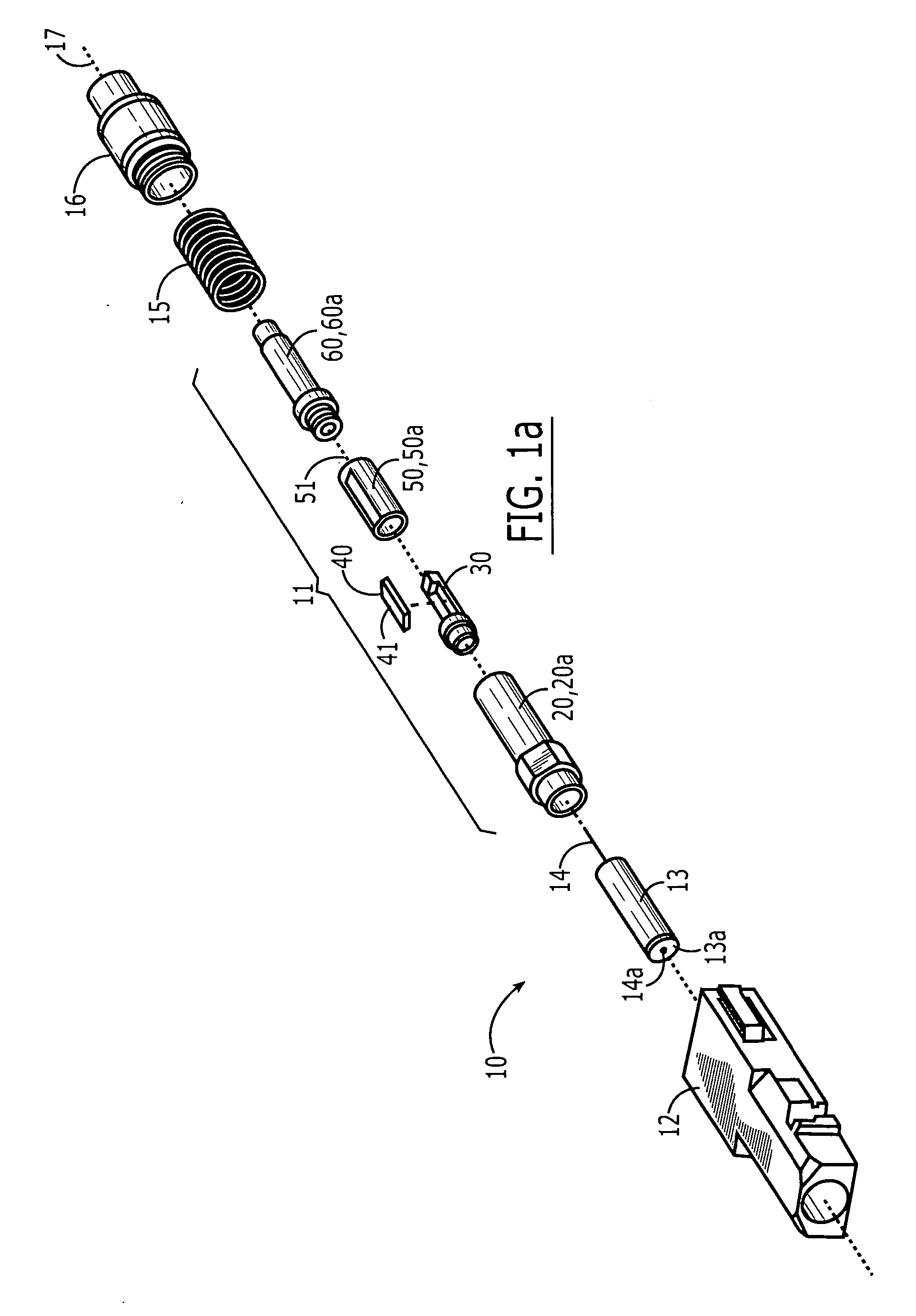
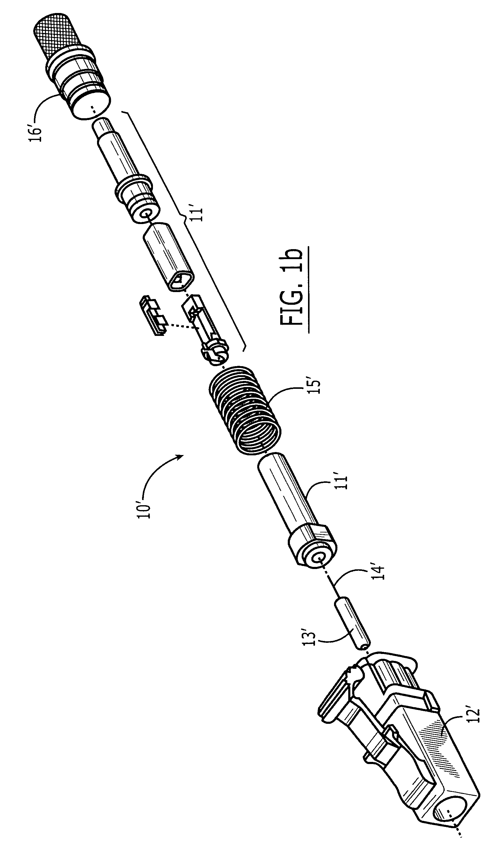
[0034] Referring to FIGS. 1a and 1b, preferred embodiments of an SC-type connector 10 and of an LC-type connector 10′ comprising the clamping assembly 11, 11′ of the present invention are shown, respectively, in exploded views. It should be understood that the present invention is not limited to an SC- and LC-type connectors and may be practiced in any conventional or later-developed connector, including, for example, traditional ST and FC-type connectors, plus small form factor designs, such as, MU, MTRJ, MPX, and MPO-type connectors. Furthermore, the clamping assembly of the present invention is not limited to connector applications and may be used in any optical application requiring a fiber to be secured to a structure. For example, the clamping assembly may be used as a splicing device to optically couple two fibers or it may be incorporated into an active device, such as a transceiver, or a passive device, such as a multiplexer, to optically couple a fiber to the device. For p...


PUM


Abstract

A clamping assembly having a top and bottom and front and back orientation, at least one optical axis, and a pre-actuated state in which a fiber is not secured to the clamping assembly and a post-actuated state in which a fiber is secured to the clamping assembly, the clamping assembly comprising: (a) a housing; (b) a platform disposed in the housing and being fixed therein both radially and axially, the platform defining a fiber-receiving channel along the optical axis to receive at least one fiber, at least a portion of the fiber-receiving channel being accessible from the top; (c) a first cam member disposed in the housing above and adjacent to the fiber-receiving channel, the first cam member being radially actuateable within the housing, the first cam member having a first cam surface; (d) a second cam member disposed in the housing and axially slidable therein, the second cam member having a second cam surface adjacent the first cam surface and configured such that, upon forward motion of the second cam member relative to the first cam member, the first cam member is urged downward as a result of a camming action between the first and second cam surfaces; and (e) an actuator disposed slidably within the housing behind and adjacent to the second cam member and configured such that, when moved forward, it forces the second cam member forward relative to the first cam member.

Description

FIELD OF INVENTION [0001] This invention relates generally to a fiber clamping assembly, and, more specifically, to a field-installable optical connector having a clamping assembly to secure a fiber to the connector. BACKGROUND OF INVENTION [0002] Optical fiber connectors are an essential part of practically all optical fiber communication systems. For instance, such connectors are used to join segments of fiber into longer lengths, to connect fiber to active devices such as radiation sources, detectors and repeaters, and to connect fiber to passive devices such as switches and attenuators. The principal function of an optical fiber connector is to optically couple a fiber with the mating device (e.g., another fiber, an active device or a passive device) by holding the end of the fiber such that the core of the fiber is axially aligned with the optical pathway of the mating device. [0003] To effect optical coupling and minimize Fresnel loss, the end of the fiber is commonly presente...

Claims


Application Information

Patent Timeline
IPC IPC(8): G02B6/36
CPCG02B6/3806G02B6/3846
Inventor MANNING, RANDY MARSHALLSAUERWEIN, LEWIS EDWARDHAYASHI, TAKEHIOERDMAN, DAVID D.
Owner COMMSCOPE TECH LLC
Why Eureka
Try Eureka