Methods and systems for coating and sealing inside piping systems

a technology of sealing and piping system, applied in the direction of manufacturing tools, other chemical processes, hollow article cleaning, etc., can solve the problems of large labor and construction costs that must be incurred for these projects, and the user's common problems with their pipes

Active Publication Date: 2007-06-07
PIPE RESTORATION TECH
View PDF28 Cites 45 Cited by
  • Summary
  • Abstract
  • Description
  • Claims
  • Application Information

AI Technical Summary

Benefits of technology

[0018] A primary objective of the invention is to provide methods, systems and devices for repairing interior walls and sealing leaks of pressurized pip...

Problems solved by technology

Large piping systems such as those used in commercial buildings, apartment buildings, condominiums, as well as homes and the like that have a broad base of users commonly develop problems with their pipes such as their water and plumbing pipes, and the like.
In addition to the large expense for the cost of the new pipes, additional problems with replacing the pipes include the immense labor and construction costs that must be incurred for these projects.
From a practical viewpoint simply getting to the problem area of the pipe to make the repair can create the largest problem.
Getting to the pipe for making repairs can require tearing up the building, cutting concrete and/or having to dig holes through floors, the foundation or the ground.
These labor intensive repair projects can include substantial demolition of a buildings walls and floors to access the existing piping systems.
For example, tearing out of the interior walls to access the pipes is an expected result of the demolition necessary to fix existing pipes.
There is usually substantial time-consuming costs for removing the debris and old pipes from the worksite.
With these projects both the cost of new pipes and the additional labor to install these pipes are required expenditures.
Further, there are additional added costs for the materials and labor to replumb these new pipes along with the necessary wall and floor repairs that must be made to clean up for the demolition effects.
For example, getting at and fixing a pipe behind drywall is not completing the repair project.
The drywall must also be repaire...

Method used


Image

  • Methods and systems for coating and sealing inside piping systems
  • Methods and systems for coating and sealing inside piping systems
  • Methods and systems for coating and sealing inside piping systems

Examples


Embodiment Construction

[0075] Before explaining the disclosed embodiments of the present invention in detail it is to be understood that the invention is not limited in its application to the details of the particular arrangements shown since the invention is capable of other embodiments. Also, the terminology used herein is for the purpose of description and not of limitation.

[0076] This invention is a Continuation-In-Part of U.S. patent application Ser. No. 11 / 246,825 filed Oct. 7, 2005, which is a Divisional of U.S. patent application Ser. No. 10 / 649,288 filed Aug. 27, 2003, now issued as U.S. pat. No. 7,160,574 on Jan. 9, 2007, which claims the benefit of priority to U.S. Provisional Patent Application 60 / 406,602 filed Aug. 28, 2002, all of which are assigned to the same assignee as the subject invention and all of which are incorporated by reference.

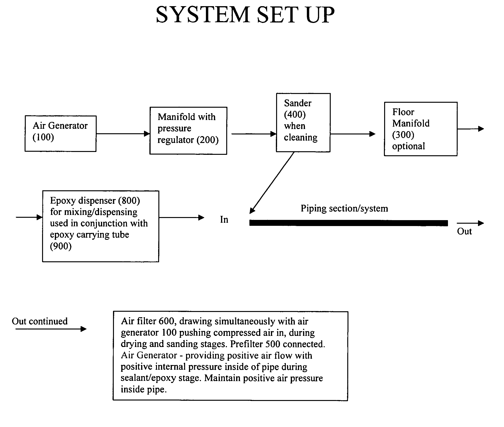
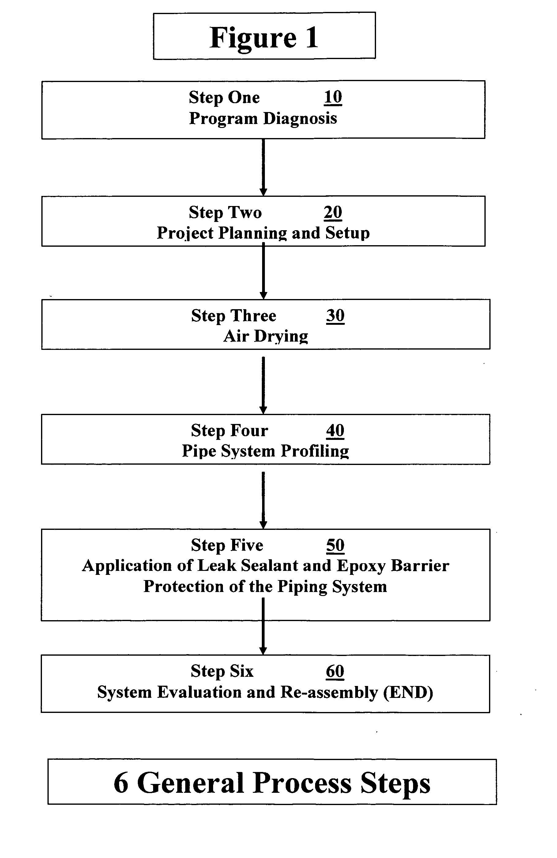
[0077]FIG. 1 shows the general six steps for a project overview for applying the barrier coating leak sealant to an existing piping system, which inclu...


PUM

PropertyMeasurementUnit
Lengthaaaaaaaaaa
Timeaaaaaaaaaa
Diameteraaaaaaaaaa

Abstract

Methods and systems for cleaning, coating and sealing leaks in existing pipes, in a single operation. A piping system can be cleaned in one pass by dry particulates forced and pulled by air throughout the piping system by a generator and a vacuum. Pipes can be protected from water corrosion, erosion and electrolysis, extending the life of pipes such as copper, steel, lead, brass, cast iron piping and composite materials. Coatings can be applied to pipes having diameters up to approximately 6″. Leak sealants of at least approximately 4 mils thick can cover insides of pipes, and can include novel mixtures of fillers and epoxy materials, and viscosity levels. A positive pressure can be maintained within the pipes during applications. Piping systems can be returned to service within approximately 96 hours.

Description

[0001] This invention is a Continuation-In-Part of U.S. patent application Ser. No. 11 / 246,825 filed Oct. 7, 2005, which is a Divisional of U.S. patent application Ser. No. 10 / 649,288 filed Aug. 27, 2003, now issued as U.S. pat. No. 7,160,574 on Jan. 9, 2007, which claims the benefit of priority to U.S. Provisional Patent Application 60 / 406,602 filed Aug. 28, 2002.FIELD OF INVENTION [0002] This invention relates to repairing leaks in pipes , and in particular to methods, systems and apparatus for repairing leaks and providing barrier protective coatings in a single operation to the interior walls of small diameter metal and plastic pressurized pipes such as pressurized drain lines, hot water lines, cold water lines, potable water lines, natural gas lines, HVAC piping systems, and fire sprinkler system lines, and the like, that are used in multi-unit residential buildings, office buildings, commercial buildings, and single family homes, and the like. BACKGROUND AND PRIOR ART [0003] L...

Claims


Application Information

Patent Timeline
IPC IPC(8): B05B13/06B24C3/32B08B9/00C08J7/043
CPCB05D3/12B05D7/222F16L58/1009Y10S118/13F16L55/18Y10S118/10F16L2101/10C09K3/12F16L2101/16C08J7/043C08J7/0427F16L58/04B05D3/0406C08J2300/00C08J2463/00C09D163/00F16L9/12F16L55/164F16L58/00F16L58/02F16L58/18
Inventor GILLANDERS, LARRYWILLIAMS, STEVELABORDE, JOHN
Owner PIPE RESTORATION TECH
Why Eureka
Try Eureka