Microreplication of transitory-image relief pattern based optically variable devices

a transitory image and relief pattern technology, applied in the field of microreplication, can solve the problems of inability to reproduce using widely available scanning or photocopying equipment, loss of all optically variable characteristics of the original, and characteristic and occasionally undesirable irridescent hu

Inactive Publication Date: 2007-06-07
KARMIC
View PDF20 Cites 10 Cited by
  • Summary
  • Abstract
  • Description
  • Claims
  • Application Information

AI Technical Summary

Benefits of technology

[0021] A further inherent advantage of the present invention relates to the aforementioned characteristic whereby a very large number of relief elements are structured simultaneously. Indeed, this characteristic opens many interesting possibilities when the relief elements forming the larger transitory image relief pattern are composed of discrete shapes, as described for example in U.S. Pat. No. 6,296,281 as opposed to what substantially amounts to long ridges as described in U.S. Pat. No. 4,033,059. Such relief patterns have been insufficiently considered to date, probably because conventional methods cannot write very large numbers of relief elements within a reasonable time frame. In accordance with the present invention, a novel type of relief structure presenting several optically variable effects and based on short interleaved prism-like relief elements (PLREs) is claimed. This novel relief structure will be described in detail in the next section.
[0022] Finally, although the Silicon wet etching technique described above for the origination of transitory image relief patterns is a very rapid and cost effective method. It is by all means not the only micromachining method which could be used. A non-exhaustive list of other similar methods composed of combinations of photolithography, an appropriate masking layer and wet or dry etching is provided in the

Problems solved by technology

OVDs are increasingly used for the marking of goods and documents because they are—in contrast with printed labels—impossible to reproduce using widely available scanning or photocopying equipment, whether colour or monochrome and regardless of equipment resolution.
Indeed copies obtained by such methods lose all the optically variable characteristics of the original due to the fixed viewing angle from which any given copy of the OVD can be made.
Finally, the close spacing of the relief pattern elements, the resulting markings always diffract light resulting in a characteristic and occasionally undesirable irridescent hue.
The aforementioned difficulties introduce a high technological barrier to the successful production of diffractive security markings, which renders them almost impervious to attempts at copying but at the same time is costly and somewhat inflexible.
Steel intaglio printing infrastructure is expensive, however the intaglio shim, typically a cylindrical steel drum incorporating laser machined relief pattern negatives, is extremely durable allowing the replication through inking of a very large number of markings.
This method however presents the disadvantage of being appropriate only for marking on paper or thin and flat plastic sheets and the additional drawback of requiring that a large number of identical markings be produced from a given shim due to its expense.
Finally, the resolution of conventional laser machining, limits the resolution of the image patterns to approximately 300 dpi.
This technology, although considerably cheaper than e-beam lithography based techniques, remains expensive due to the very small production runs of sensors and other devices it is commonly used to fabricate.
It is equally non-obvious to OVD and DOVID specialists since the latter subject springs from the technical field of laser holography and development there has been limited to finding a technology—in their case e-beam lithography—with a sufficiently high spatial resolution to exploit holographic and diffraction techniques.
Apart from the fact that OVDs and transitory-image relief patterns are not specifically referred to in the disclosure, its principal drawback is that it is far too general and thus complex for the application which is the object of the present invention, the process presented taking several full days to complete.
Furthermore, the method disclosed in WO95 / 22448 does not exploit the full range of optically variable characteristics conceivable upon careful consideration of the various micromachining methods available, which are by no means limited to Silicon substrates for example.

Method used


Image

  • Microreplication of transitory-image relief pattern based optically variable devices
  • Microreplication of transitory-image relief pattern based optically variable devices
  • Microreplication of transitory-image relief pattern based optically variable devices

Examples


first embodiment

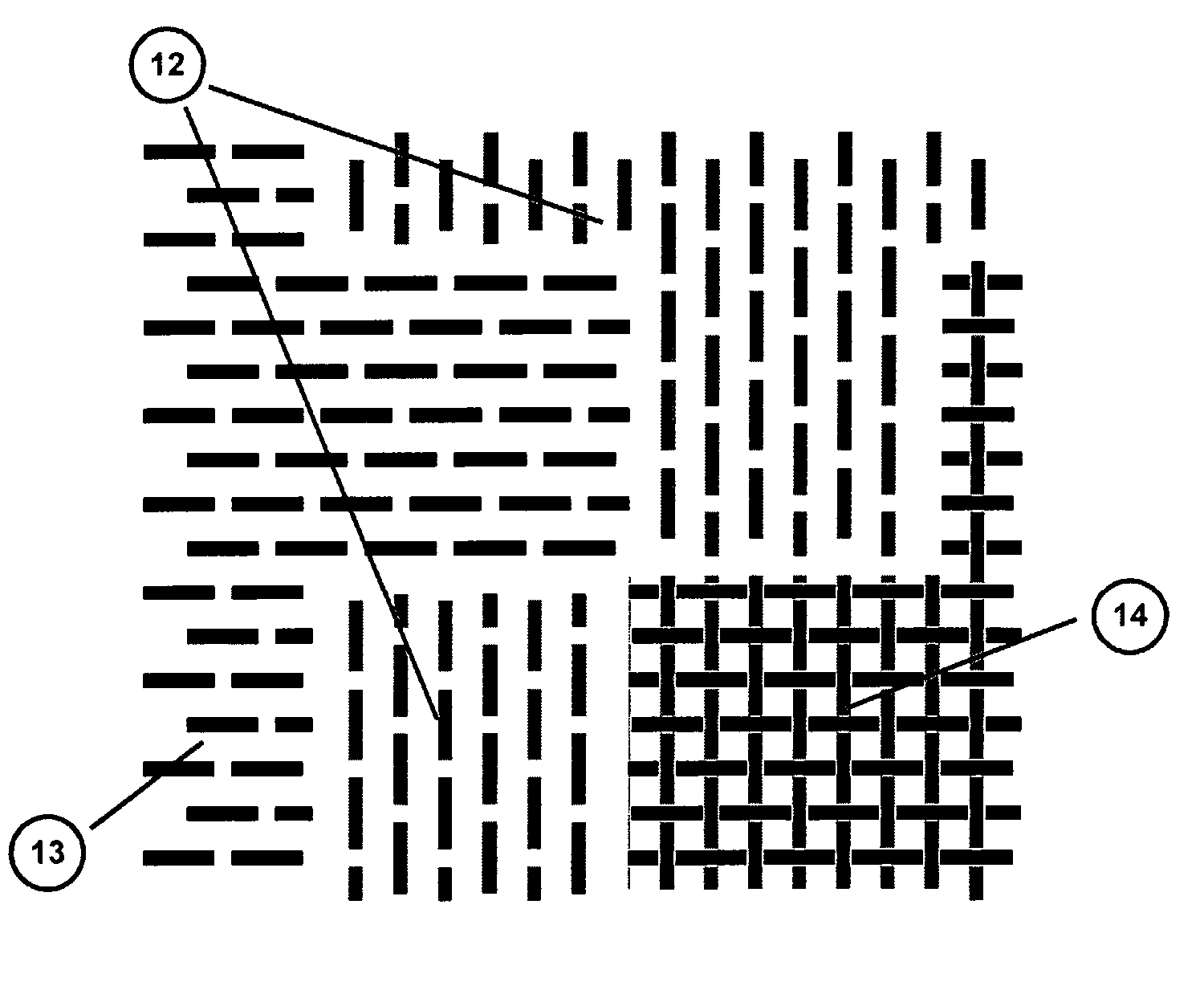
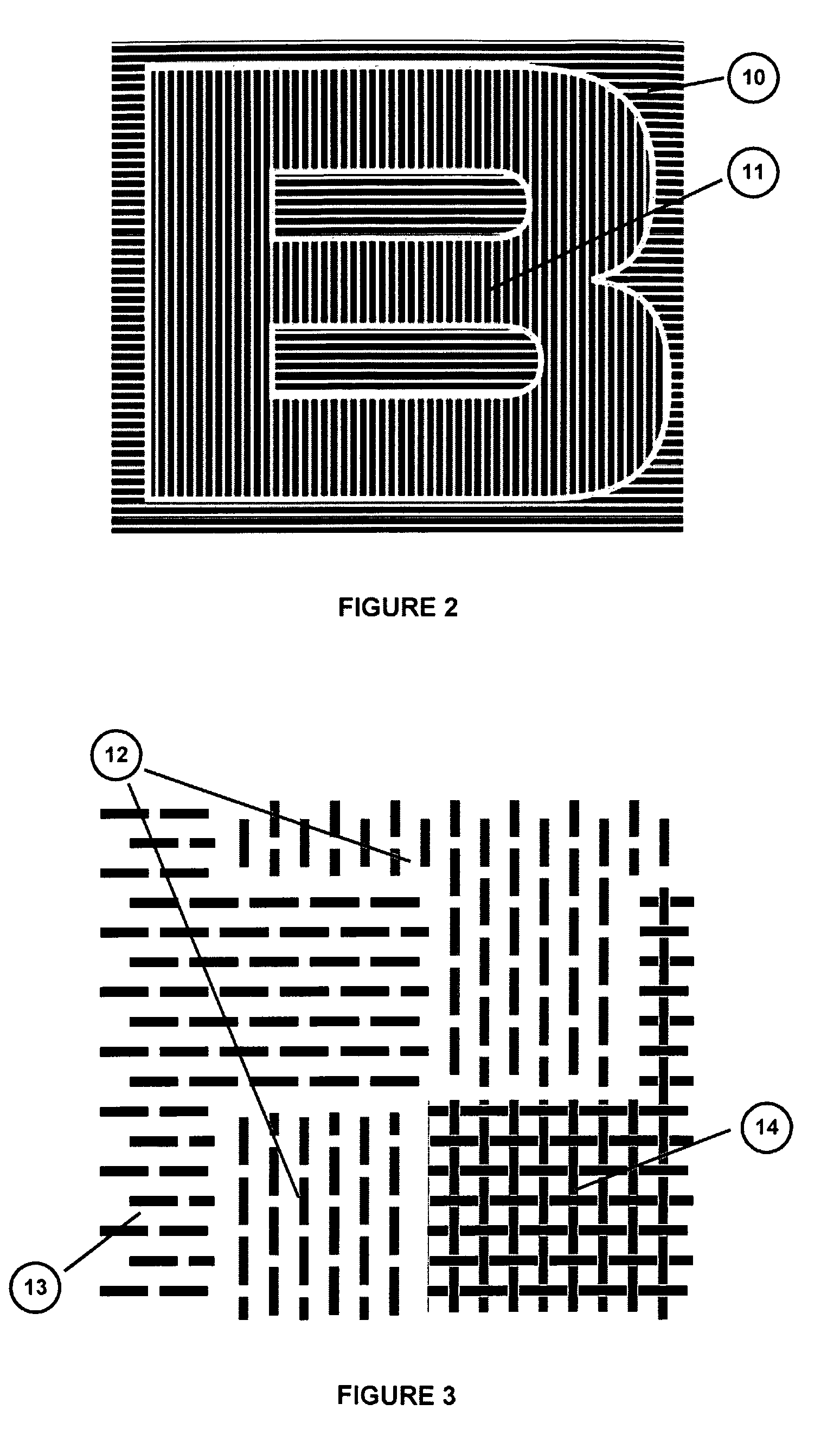
[0026] In accordance with the present invention, the “single wet etching step” method described above allows the patterning of a Silicon origination shim containing the negative of relief elements, which can be of different depths and which are formed during the same micromachining process. Said relief elements can be disposed spatially at will on the photomask, in such a way that, at the end of the entire process described above, the replicated pattern will consist of distinguishable foreground and background areas which cooperate to form the transitory images described in FIGS. 6,7,8, 12 and 13 of U.S. Pat. No. 4,033,059 or combinations thereof. This first embodiment can also be used to realize transitory image relief patterns based on PRLEs as described in detail below. Finally, the planes forming the sides of the V-groove relief element negatives on the shim, when replicated, form a mirror-like surface which yields a further optically variable contrast-switching effect between ...

third embodiment

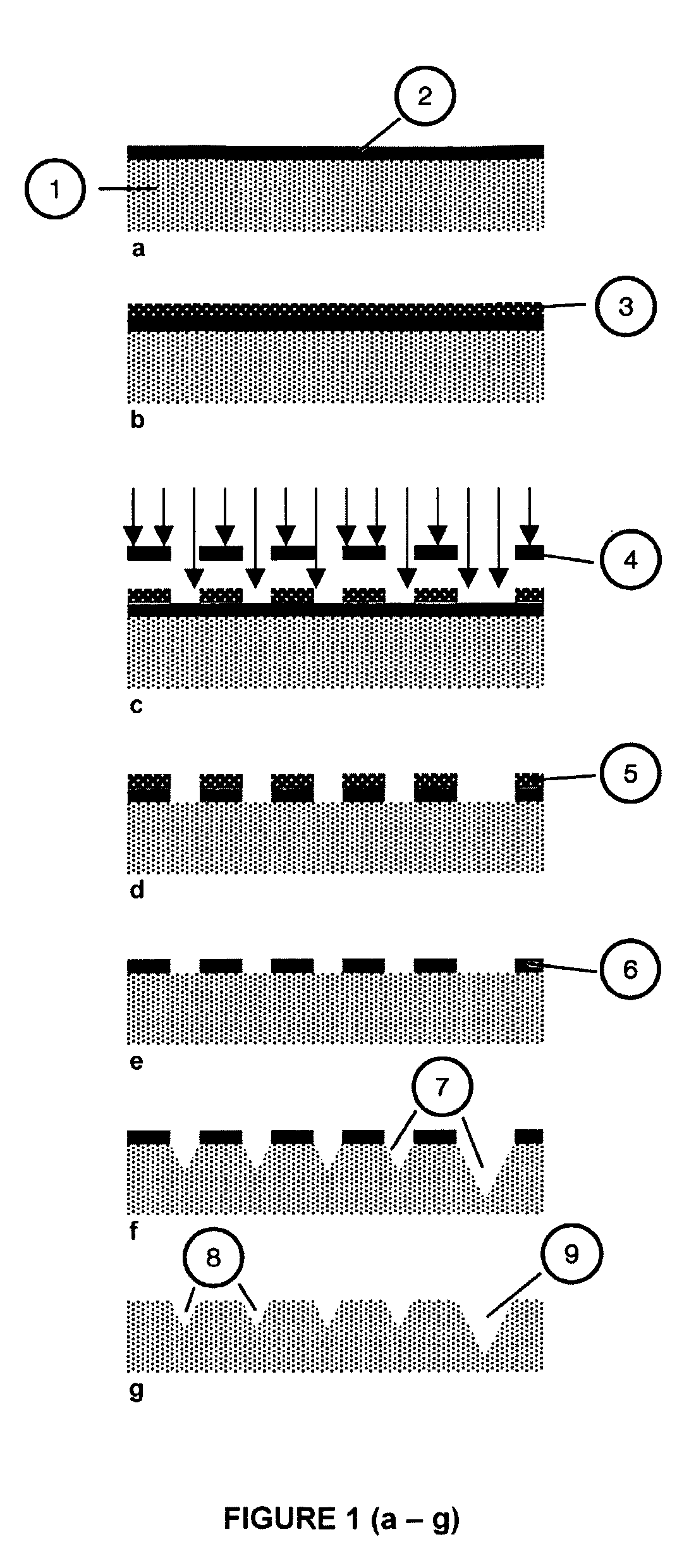
[0029] Although wet etching of the bulk Silicon is the preferred method for the structuring of the Silicon origination shim, the wet etching steps described in the previous two embodiments of the present invention can also be replaced, in the present invention, by dry etching of the Silicon substrate using any of several suitable dry etch chemistries well-known in the technical field of Silicon micromachining. One such dry etching chemistry consists of using Sulphur Hexafluoride (SF6) gas plasma. It must be noted however that replicated markings of shims fabricated using dry etching of the Silicon substrate do not exhibit the specular reflection effect previously described for replicas of wet-etched shims.

[0030] In a fourth and final embodiment of the present invention. Micromachining processes very similar to those described above may be used to obtain an origination shim, in materials other than Silicon, containing transitory-image type relief patterns. Indeed a wide variety of ma...


PUM

PropertyMeasurementUnit
timeaaaaaaaaaa
relief depthaaaaaaaaaa

Abstract

The invention concerns a method for the replication by hot-embossing, hot-stamping or plastic injection moulding of an optically variable transitory image relief pattern characterized by the use of a Silicon origination shim fabricated through a micromachining process. The invention also comprises objects and structures obtained according to said method.

Description

FIELD OF THE INVENTION [0001] The invention relates to the replication, by moulding, hot embossing or other comparable techniques, of an optically variable transitory-image relief pattern. The resulting, microreplicated, optically variable relief pattern is destined for, but not limited to use as a marking for the decoration, protection and end-customer authentication of branded products. PRIOR ART [0002] Several solutions are currently available for the decoration, protection and customer authentication of branded products. They include: (i) offset printing based techniques for applying logos such as thermal pattern transfer and screen printing, (ii) security printing techniques such as intaglio printing with security inks, (iii) serialised, machine readable markings such as bar codes and finally (iv) optically variable markings, conventionally denoted as optically variable devices (OVDs) such as holographic seals and diffractive or interference elements. Each of these techniques a...

Claims


Application Information

Patent Timeline
Patent Type & Authority Applications(United States)
IPC IPC(8): H01L21/00
CPCB29C45/372B29C59/022G03F7/0017
Inventor LEUNG KI, YIT-SHUN
Owner KARMIC
Why Eureka
Try Eureka