Radio-frequency circuit realizing stable operation

a radio frequency circuit and stable technology, applied in the field of radio frequency circuits, can solve the problem of high impedance of the parasitic oscillation frequency of the industry, and achieve the effect of stable operation

Inactive Publication Date: 2007-06-07
ALPS ALPINE CO LTD
View PDF15 Cites 1 Cited by
  • Summary
  • Abstract
  • Description
  • Claims
  • Application Information

AI Technical Summary

Benefits of technology

[0014] According to the embodiments of the present invention, parasitic oscillation of a radio-frequency amplifier circu...

Problems solved by technology

Therefore, the inductor presents high impedance at the parasi...

Method used


Image

  • Radio-frequency circuit realizing stable operation
  • Radio-frequency circuit realizing stable operation
  • Radio-frequency circuit realizing stable operation

Examples


Embodiment Construction

[0018] Embodiments of the present invention will be described in detail with reference to the accompanying drawings.

[0019] An embodiment of the present invention applied to an up-converter of a television signal transmitter will be described.

[0020] The television signal transmitter according to the embodiment of the present invention has the same overall structure as that of a television signal transmitter shown in FIG. 3. That is, the television signal transmitter includes a second mixer 11, a local oscillator 12, a filter 13, a pre-amplifier 14 serving as a radio-frequency amplifier circuit, a variable attenuator 15, a plural-stage amplifier 16, a band-pass filter 17, and a power amplifier 18.

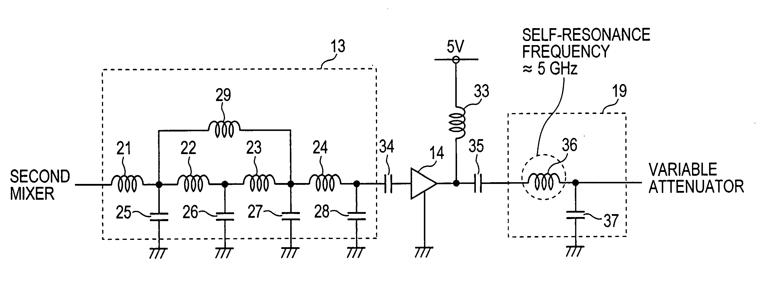
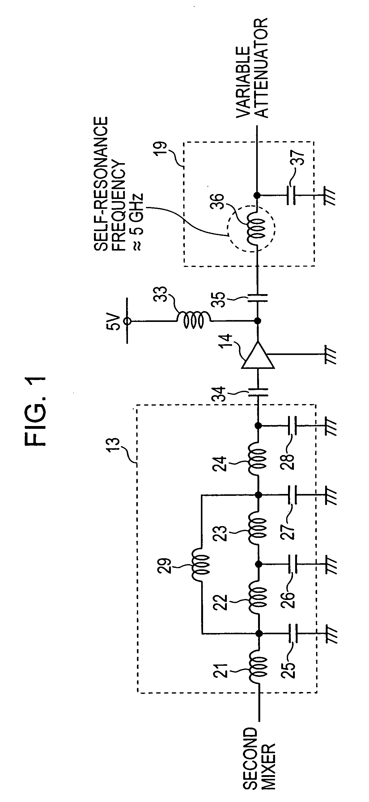
[0021]FIG. 1 is a circuit diagram showing the structure of portions including the filter 13 and the pre-amplifier 14.

[0022] The filter 13 realizes desired characteristics by combining a plurality of inductors and capacitors. Specifically, inductors 21 to 24 are cascade-connected in series...


PUM


Abstract

A television signal transmitter has an up-converter provided with a pre-amplifier and an impedance matching circuit subsequent to the pre-amplifier. The self-resonance frequency of an inductor included in the impedance matching circuit, which is connected in series to a signal line, is set to a parasitic oscillation frequency (5 GHz) of the pre-amplifier. The self-resonance frequency of an inductor of a filter provided prior to the pre-amplifier, which is connected in series to the signal line, is set to the parasitic oscillation frequency (5 GHz) of the pre-amplifier.

Description

BACKGROUND OF THE INVENTION [0001] 1. Field of the Invention [0002] The present invention relates to a radio-frequency circuit in which a variable-load circuit is connected to the input or output side of a radio-frequency amplifier circuit. [0003] 2. Description of the Related Art [0004] A known television signal transmitter located at a community antenna television (CATV) station up-converts a television signal in an intermediate frequency band (hereinafter referred to as an “IF signal”) into a television signal of a channel to be transmitted (hereinafter referred to as an “RF signal”) and transmits the RF signal to a cable connected to the television signal transmitter (for example, see Japanese Unexamined Patent Application Publication No. 2001-94889). [0005]FIG. 3 is a circuit diagram showing the structure of main portions of a known television signal transmitter. In the television signal transmitter shown in FIG. 3, an IF signal frequency-converted by a first mixer (not shown) ...

Claims


Application Information

Patent Timeline
IPC IPC(8): H04B1/04H04N7/16H03F1/08H03F3/19
CPCH04B1/0458
Inventor KUDO, YASUHARU
Owner ALPS ALPINE CO LTD
Why Eureka
Try Eureka