Interface switch for distributed energy resources

a distributed energy resource and interface switch technology, applied in the direction of switches operated by abnormal voltage/current products/phase angles, substation equipment, relays, etc., can solve the problems of waste of process materials, productivity, and other costs to restart a production line, and the public power grid remains subject to occasional failures

Active Publication Date: 2007-06-07
WISCONSIN ALUMNI RES FOUND
View PDF19 Cites 29 Cited by
  • Summary
  • Abstract
  • Description
  • Claims
  • Application Information

AI Technical Summary

Benefits of technology

[0026] When both conditions are satisfied, in a switch and method according to the invention, temporary reverse power flows, power surges, voltage transients, and other undesirable effects can be avoided, reduced, or minimized when the interface switch closes. An interface switch and method according to the invention can satisfy these conditions using several different techniques, as discussed below in more detail.

Problems solved by technology

At the same time, the public power grid remains subject to occasional failures, even in the United States.
These problems with the capacity and reliability of the public power grid have driven the development of distributed energy resources (DER), small independent power generation and storage systems which may be owned by, and located near, consumers of electrical power.
For example, an interruption of power to a hospital can have life-threatening consequences.
Similarly, when power to a factory is interrupted, the resulting losses, for example in productivity, wasted material in process that must be scrapped, and other costs to restart a production line, can be catastrophic.
Geographically distributed sources of power, such as wind, solar, or hydroelectric power, may be too limited or intermittent to be used as the basis for a centralized power plant.

Method used


Image

  • Interface switch for distributed energy resources
  • Interface switch for distributed energy resources
  • Interface switch for distributed energy resources

Examples


Embodiment Construction

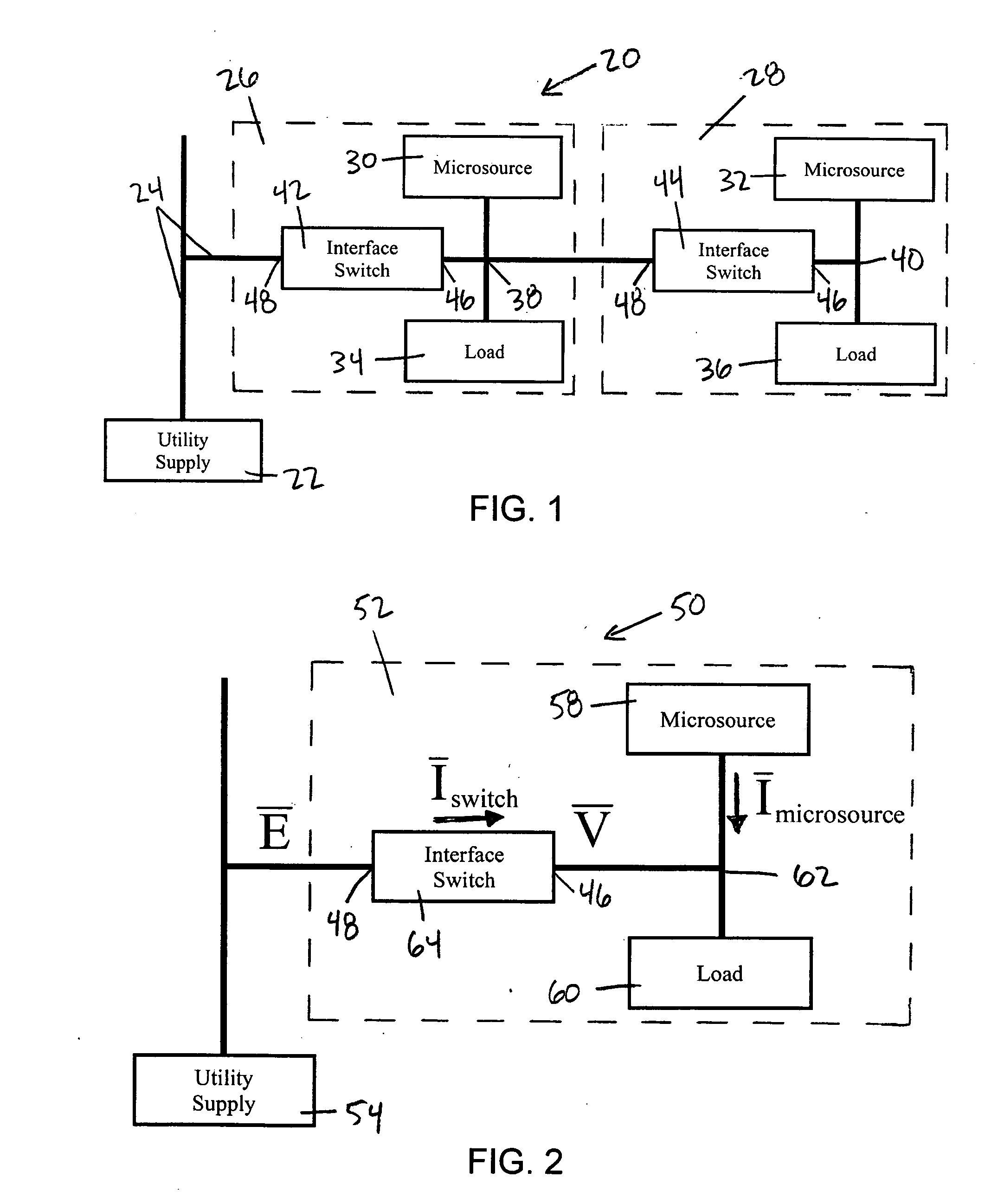
[0046]FIG. 1 is a diagram of an exemplary distributed energy resource system, indicated generally at 20, that includes two microgrids. The exemplary distributed energy resource system 20 includes at least one utility supply 22 electrically connected by one or more feeder lines 24 to a first microgrid 26 and a second microgrid 28.

[0047] The exemplary first microgrid 26, connected to the first interface switch 42, includes a microsource 30 and a microsource bus 38, and may also include a load 34, although this is not required. The exemplary second microgrid 28, connected to the second interface switch 44, is similar, and includes a microsource 32 and a microsource bus 40, and may optionally include a load 36. Each interface switch 42, 44 has an internal terminal 46 electrically connected to a microsource bus 38, 40 (respectively) and an external terminal 48 electrically connected to a supply bus, for example a feeder line 24 from a utility supply 22.

[0048] The exemplary distributed ...


PUM


Abstract

A method and apparatus for an interface switch having an external terminal electrically connected to an AC voltage E at a frequency ω0 (for example a utility supply), and an internal terminal electrically connected to an AC voltage V at a selectable frequency ω (for example a microsource). In one embodiment, the interface switch is closed when the voltage difference between E and V and the relative phase angle δEV between E and V are both small, and when the higher frequency voltage (as between E and V) leads the lower frequency voltage. In another embodiment, the interface switch is closed when the envelope of the voltage difference between E and V reaches a local minimum at a point of inflection.

Description

REFERENCE TO GOVERNMENT RIGHTS [0001] This invention was made with United States government support awarded by the following agencies: [0002] DOE EEC-9615 778 [0003] CEC 6703843 [0004] The United States has certain rights in this invention.FIELD OF THE INVENTION [0005] The present invention relates generally to power and distributed energy resource (DER) systems and methods, and more particularly to interface switch devices and methods therefor. BACKGROUND OF THE INVENTION [0006] In the United States and around the world, the demand for electrical power continues to grow. At the same time, the public power grid remains subject to occasional failures, even in the United States. These problems with the capacity and reliability of the public power grid have driven the development of distributed energy resources (DER), small independent power generation and storage systems which may be owned by, and located near, consumers of electrical power. [0007] One motivating factor is that distri...

Claims


Application Information

Patent Timeline
Patent Type & Authority Applications(United States)
IPC IPC(8): H04B1/38H04M1/00
CPCH02J3/38
Inventor LASSETER, ROBERT H.PIAGI, PAOLO
Owner WISCONSIN ALUMNI RES FOUND
Why Eureka
Try Eureka