Dynamic synchronizer simulation

a synchronizer and dynamic technology, applied in the field of synchronizer modules and methods, can solve the problems of inability to detect design errors in advance, synchronization problems may still occur, and complex digital circuitry, etc., and achieve the effect of better modelling real-silicon behaviour

Inactive Publication Date: 2007-06-07
GLOBALFOUNDRIES INC
View PDF15 Cites 11 Cited by
  • Summary
  • Abstract
  • Description
  • Claims
  • Application Information

AI Technical Summary

Benefits of technology

[0013] An improved synchronization technique is provided that may allow for better modelling real-silicon behaviour for simulation to detect signal synchronization problems earlier in the flow.

Problems solved by technology

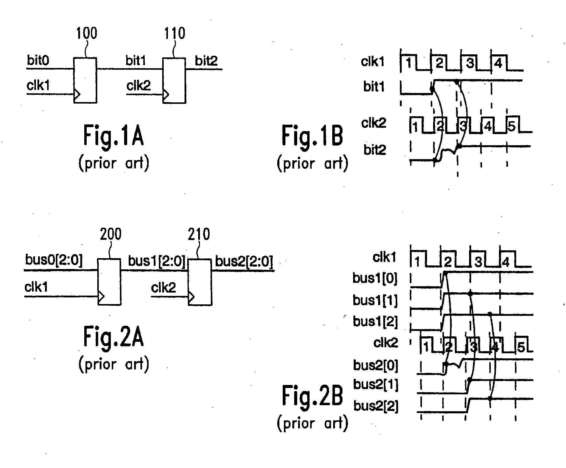
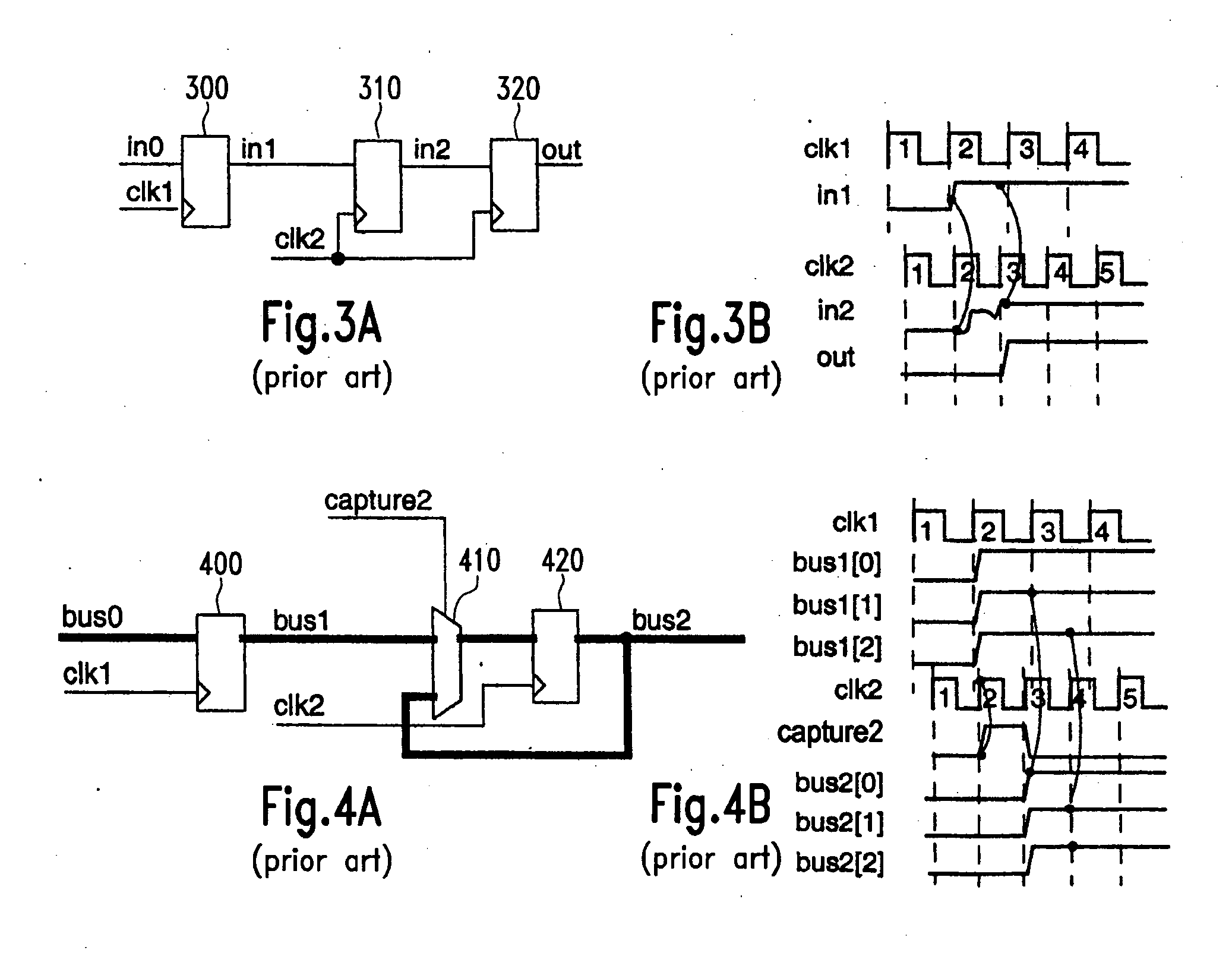
Thus, while clock domain crossing signal synchronization is already possible in the prior art, there are a number of structural and functional issues that may be sources of potential errors.
For instance, synchronization problems may still occur if the overall circuitry design includes errors or design flaws which are difficult to observe in advance.
As digital circuitry usually becomes quite complex, it is often not possible to detect such design errors in advance.
This may then lead to functional errors which are only detected late in the design cycle, or even worse, during post-silicon verification.
Due to the generally unreliable nature of such error,it is then even more difficult to find the source of the error, thus leading to increased circuit development costs.

Method used


Image

  • Dynamic synchronizer simulation
  • Dynamic synchronizer simulation
  • Dynamic synchronizer simulation

Examples


Embodiment Construction

[0045] The illustrative embodiments of the present invention will be described with reference to the figure drawings wherein like elements and structures are indicated by like reference numbers.

[0046] Before discussing in more detail the synchronization modules of the embodiments which provide a dynamic verification of single-bit and bus synchronization, it is referred to FIG. 5, which illustrates a static verification technique that may be used in connection with the embodiments. In this approach, the whole design structure is mapped onto a graph model which is built from vertex and edge elements. Vertices may be flops (denoted as “f” in FIG. 5) and combinational elements (denoted as “c”). Edges are depicted as wires in the graph model.

[0047] In the static verification approach, the model is partitioned into clock domains and stage levels. As may be seen from FIG. 5, the present example illustrates four different levels. Taking the example of bus synchronization, buses may be ide...


PUM


Abstract

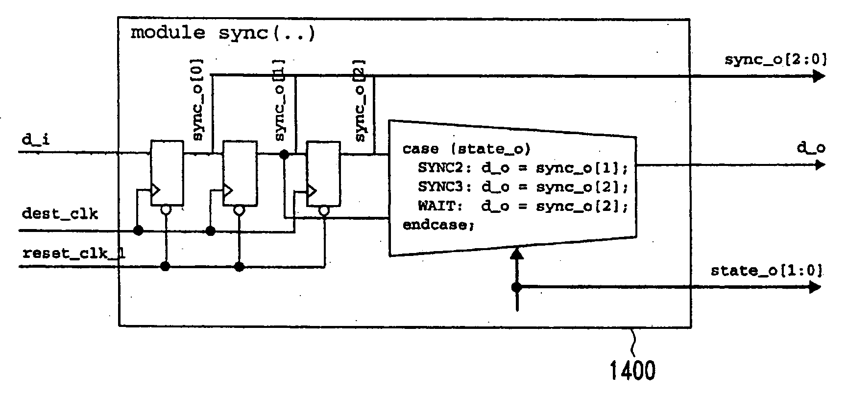
A synchronizer module is provided that may be used to facilitate the simulation of circuitry having clock domain crossing signals. A multiple-stage synchronizer may be used where at least one of the multiple synchronizer stages is dynamically enabled and disabled. The synchronizer module may have a delay unit for selectively applying a variable delay. This may allow for better modelling the real-silicon behaviour for simulation purposes to detect signal synchronization problems earlier in the flow, for instance during RTL (Register Transfer Level) design.

Description

BACKGROUND OF THE INVENTION [0001] 1. Field of the Invention [0002] The invention generally relates to synchronizer modules and methods, and particularly to synchronizers which may be simulated in an RTL (Register Transfer Level) simulation. [0003] 2. Description of the Related Art [0004] Many integrated circuit chips exist which have clock driven digital circuits which form more than one clock domain. In such devices, a first part of the digital circuitry is driven by a first clock, while a second part is driven by a second clock. The second clock may be different from the first clock and may even come from a different source. Examples of devices having multiple clock domains are computer chipsets, USB (Universal Serial Bus) host controllers, and WLAN (Wireless Local Area Network) receiver or transceiver devices. A number of other fields where an integrated circuit chip may have more than one clock domain exist in the state of the art. [0005] In many applications, the digital circu...

Claims


Application Information

Patent Timeline
Patent Type & Authority Applications(United States)
IPC IPC(8): G06F17/50G06G7/62
CPCG06F17/5022G06F30/33
Inventor LANGER, MARKSHEELEY, NATHANHESSE, KAYHARTON, TRACY
Owner GLOBALFOUNDRIES INC
Why Eureka
Try Eureka