Electronic apparatus including removable dust catcher

a dust catcher and electronic technology, applied in the direction of electrical apparatus casings/cabinets/drawers, instruments, separation processes, etc., can solve the problems of airflow obstruction, cpu temperature rise, and failure of the normal operation of the cpu

Inactive Publication Date: 2007-06-14
FUJITSU CLIENT COMPUTING LTD
View PDF32 Cites 90 Cited by
  • Summary
  • Abstract
  • Description
  • Claims
  • Application Information

AI Technical Summary

Benefits of technology

[0006] It is accordingly an object of the present invention to provide an electronic apparatus contributing to the maintenance of an efficient radiation of heat from a heat radiating...

Problems solved by technology

The airflow is thus obstructed.
The temperature of CPU thus inevitably rises.
The ...

Method used


Image

  • Electronic apparatus including removable dust catcher
  • Electronic apparatus including removable dust catcher
  • Electronic apparatus including removable dust catcher

Examples


Embodiment Construction

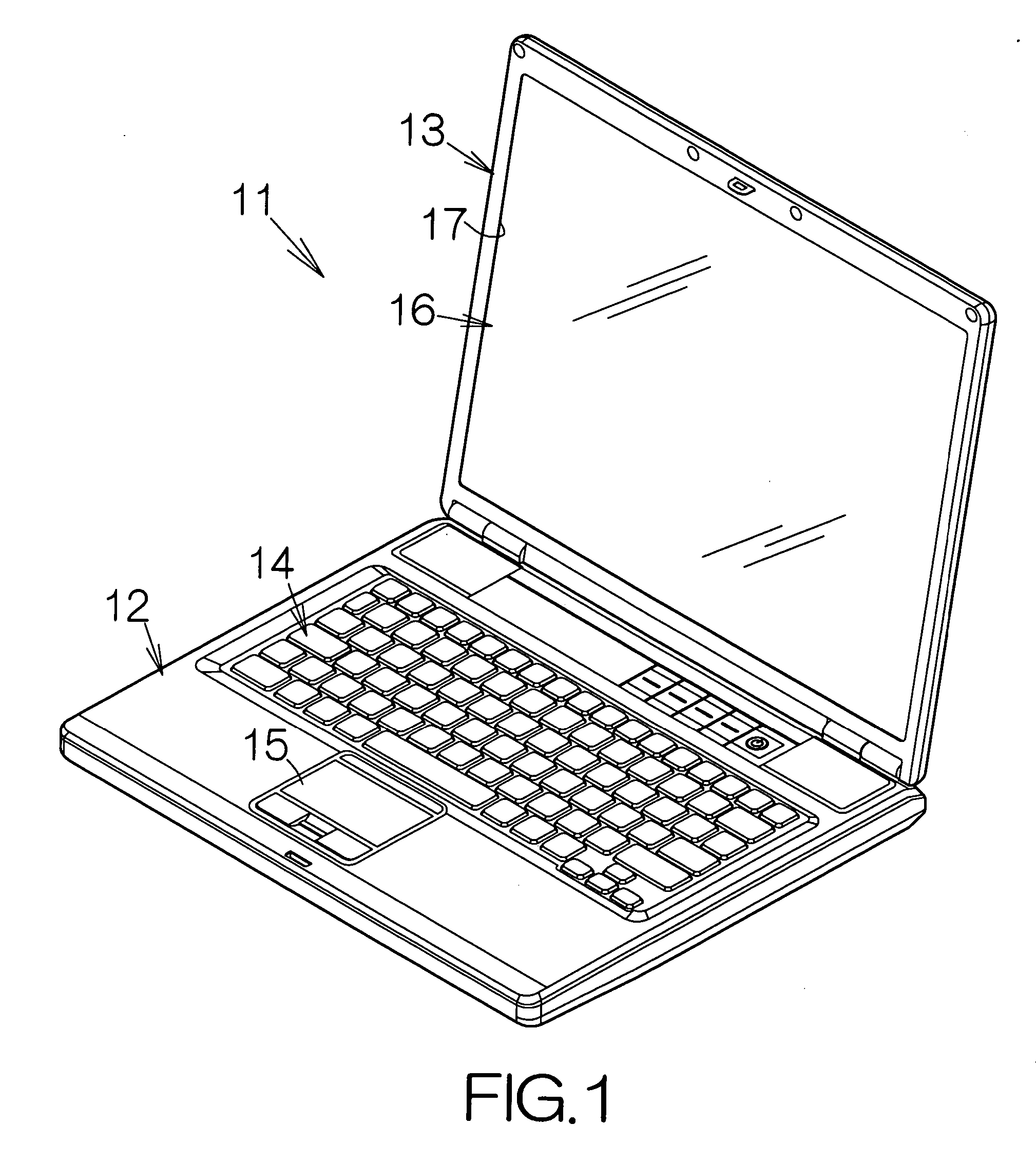
[0032]FIG. 1 schematically illustrates a notebook personal computer 11 as a specific example of an electronic apparatus according to the present invention. The notebook personal computer 11 includes a thin main body 12 and a display enclosure 13 pivotably coupled to the main body 12. Input devices such as a keyboard 14 and a pointing device 15 are embedded in the front surface of the main body 12. Users manipulate the keyboard 14 and / or the pointing device 15 to input commands and / or data.

[0033] A display device such as a liquid crystal display (LCD) panel module 16 is enclosed in the display enclosure 13, for example. The screen of the LCD panel module 16 gets exposed in a window opening 17 defined in the display enclosure 13. Text data and graphics are displayed on the screen. Users can see the ongoing operation of the notebook personal computer 11 based on the displayed text data and graphics. The display enclosure 13 can be superimposed on the main body 12 through a pivotal mov...


PUM

PropertyMeasurementUnit
Speedaaaaaaaaaa
Heataaaaaaaaaa
Tackinessaaaaaaaaaa

Abstract

A fan is enclosed in the enclosure of an electronic apparatus. The fan discharges air out of a ventilation opening of the fan itself. Heat radiating fins are located in an air passage extending from the ventilation opening. A dust catcher is removably mounted in an opening of the enclosure from the outside of the enclosure. The dust catcher is located in the air passage between the heat radiating fins and the ventilation opening. The dust catcher serves to catch the dust in the air passage. The dust catcher is removed from the enclosure along with the dust. The dust is thus reliably cleared from the air passage. The dust catcher can then be cleaned. The cleaned dust catcher can again be set in the opening of the enclosure. Airflow of a sufficient amount is in this manner always kept in the air passage.

Description

BACKGROUND OF THE INVENTION [0001] 1. Field of the Invention [0002] The present invention relates to an electronic apparatus such as a notebook personal computer. In particular, the invention relates to an electronic apparatus comprising: a fan discharging air out of a ventilation opening of the fan; and a heat radiating fin or fins located in an air passage extending from the ventilation opening of the fan. [0003] 2. Description of the Prior Art [0004] A fan is often enclosed in the enclosure of a notebook personal computer, for example. The fan generates airflow toward an air outlet defined in the enclosure. Heat radiating fins are located in an air passage extending from the ventilation opening of the fan. A heat pipe is coupled to the heat radiating fins. The heat pipe serves to transfer heat of a central processing unit, CPU, to the heat radiating fins, for example. The airflow in the air passage serves to absorb the heat from the heat radiating fins. The airflow having the hea...

Claims


Application Information

Patent Timeline
IPC IPC(8): H05K7/20
CPCB01D46/10B01D2279/45G06F1/203
Inventor HATTORI, MASAHIKOOHNISHI, MASUOTACHIKAWA, TADANORINISHIZAWA, MASATOSHIHARADA, TOMOKINAKAGAI, GOROKATO, TOYOHIRO
Owner FUJITSU CLIENT COMPUTING LTD
Why Eureka
Try Eureka