
Packaging device and packaging method for hollow cathode type sputtering target

a hollow cathode sputtering and packaging device technology, applied in the direction of liquid handling, applications, caps, etc., can solve the problems of bag burst, insufficient preventive measures for oxidization, and difficult structure, so as to prevent humidity and oxidization, maintain the clean target surface, and prevent the adhesion of dust and dir

Active Publication Date: 2007-06-14
JX NIPPON MINING& METALS CORP
View PDF8 Cites 11 Cited by
  • Summary
  • Abstract
  • Description
  • Claims
  • Application Information

AI Technical Summary

Benefits of technology

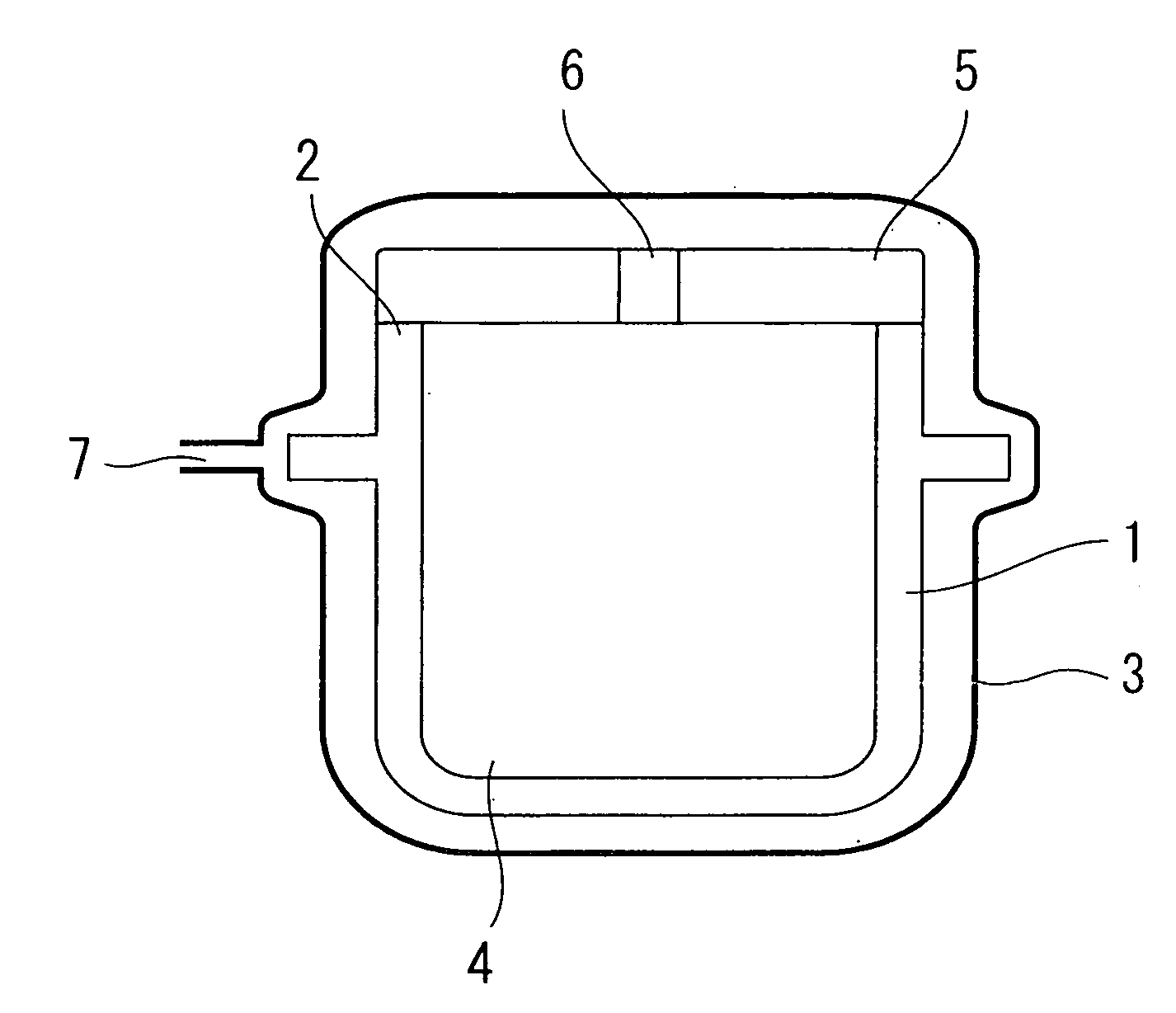
[0021] The present invention yields a superior effect in that it is capable of evacuating the void of the target via the through-holes provided to the cover upon performing vacuum suction to the hollow cathode sputtering target covered with a resin bag, and, in the void to become the eroded portion of the target, it is possible to maintain the cleansed target surface without even once coming in contact with the packaging resin. Therefore, a significant effect is yielded in that it is possible to further prevent the adhesion of dust and dirt and prevent humidity and oxidization in comparison to conventional methods.

Problems solved by technology

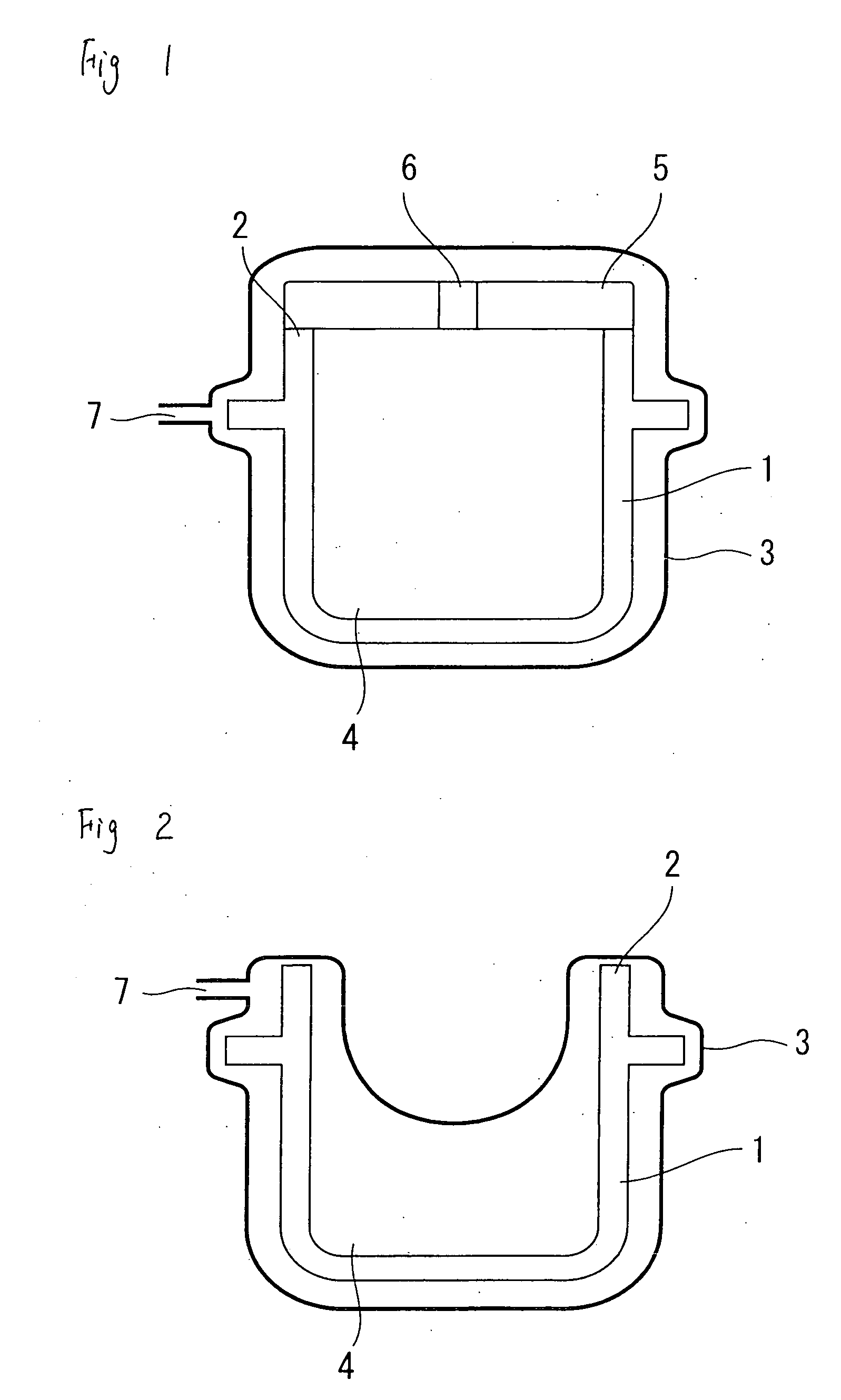
Nevertheless, when this is applied to a hollow cathode sputtering target, there is a difficult problem in terms of structure.
As shown in FIG. 2, a bag 3 adheres (is tethered to) a peripheral edge 2 of a hollow cathode sputtering target 1, a void 4 cannot be sucked sufficiently, and there is a problem in that this is an insufficient preventive measure for preventing oxidization.
Further, since the void 4 will be decompressed, there is another problem in that the resin bag will be pulled inward, and tension thereof could cause the bag to burst.

Method used


Image

  • Packaging device and packaging method for hollow cathode type sputtering target
  • Packaging device and packaging method for hollow cathode type sputtering target

Examples


Embodiment Construction

[0024] The hollow cathode sputtering target of the present invention is now explained with reference to FIG. 1. FIG. 1 is a view showing a frame format of a representative shape of the hollow cathode sputtering target 1.

[0025] Here, although the cross section is taking on a U-shape, there is no particular limitation on this shape, and the present invention is applicable to all targets as long as the target has voids inside; for instance, targets having a W-shaped cross section. The present invention covers all such shapes.

[0026] Further, there is no particular limitation on the target material, and various metals, alloys, and ceramics of silicon compounds and oxides may be used. In order to manufacture a hollow body (cup shape), processing methods such as forging, rolling, thread rolling, deep drawing and the like are performed. There is also no limitation on these manufacturing methods.

[0027] Generally, the inner face of the hollow cathode sputtering target 1 becomes the eroded ...


PUM

PropertyMeasurementUnit
sizeaaaaaaaaaa
transparentaaaaaaaaaa
vacuum suctionaaaaaaaaaa

Abstract

Provided are a packaging device and packaging method of a hollow cathode sputtering target which installs, in the hollow cathode sputtering target, a cover of a size capable of covering a void of the target; provides one or more through-holes to the cover; places a resin bag over them, and performs vacuum suction to the inside of the bag. This packaging device and packaging method of a hollow cathode sputtering target is capable of performing vacuum suction even to the inside of the hollow portion covered with the resin bag.

Description

TECHNICAL FIELD [0001] The present invention relates to a packaging device and packaging method of a hollow cathode sputtering target capable of preventing the adhesion of dust and dirt, and preventing humidity and oxidization. BACKGROUND [0002] In recent years, the sputtering method for forming a film from materials such as metal or ceramics has been used in numerous fields such as electronics, corrosion resistant materials and ornaments, catalysts, as well as in the manufacture of cutting / grinding materials and abrasion resistant materials. [0003] Although the sputtering method itself is a well-known method in the foregoing fields, recently, particularly in the field of electronics, a sputtering target suitable for forming films of complex shapes and forming circuits is in demand. [0004] Under the foregoing circumstances, a hollow cathode sputtering target has been proposed in recent days. This target takes on a cup shape, and the name “hollow cathode sputtering target” derives fr...

Claims


Application Information

Patent Timeline
Patent Type & Authority Applications(United States)
IPC IPC(8): C23C14/00B65B31/04B65D81/20
CPCB65B31/04B65D81/2023H01J37/342B65D81/20
Inventor OKABE, TAKEONAGASAWA, MASARU
Owner JX NIPPON MINING& METALS CORP
Learn More