
Electrically conductive adhesives

a technology of electrically conductive adhesives and adhesives, which is applied in the direction of non-metal conductors, conductors, dielectric characteristics, etc., can solve the problems of high processing temperature of lead-free alloy solders, new challenge for reliable assembly of microelectronics components, and high material cos

Inactive Publication Date: 2007-06-14
GENERAL ELECTRIC CO
View PDF16 Cites 140 Cited by
  • Summary
  • Abstract
  • Description
  • Claims
  • Application Information

AI Technical Summary

Benefits of technology

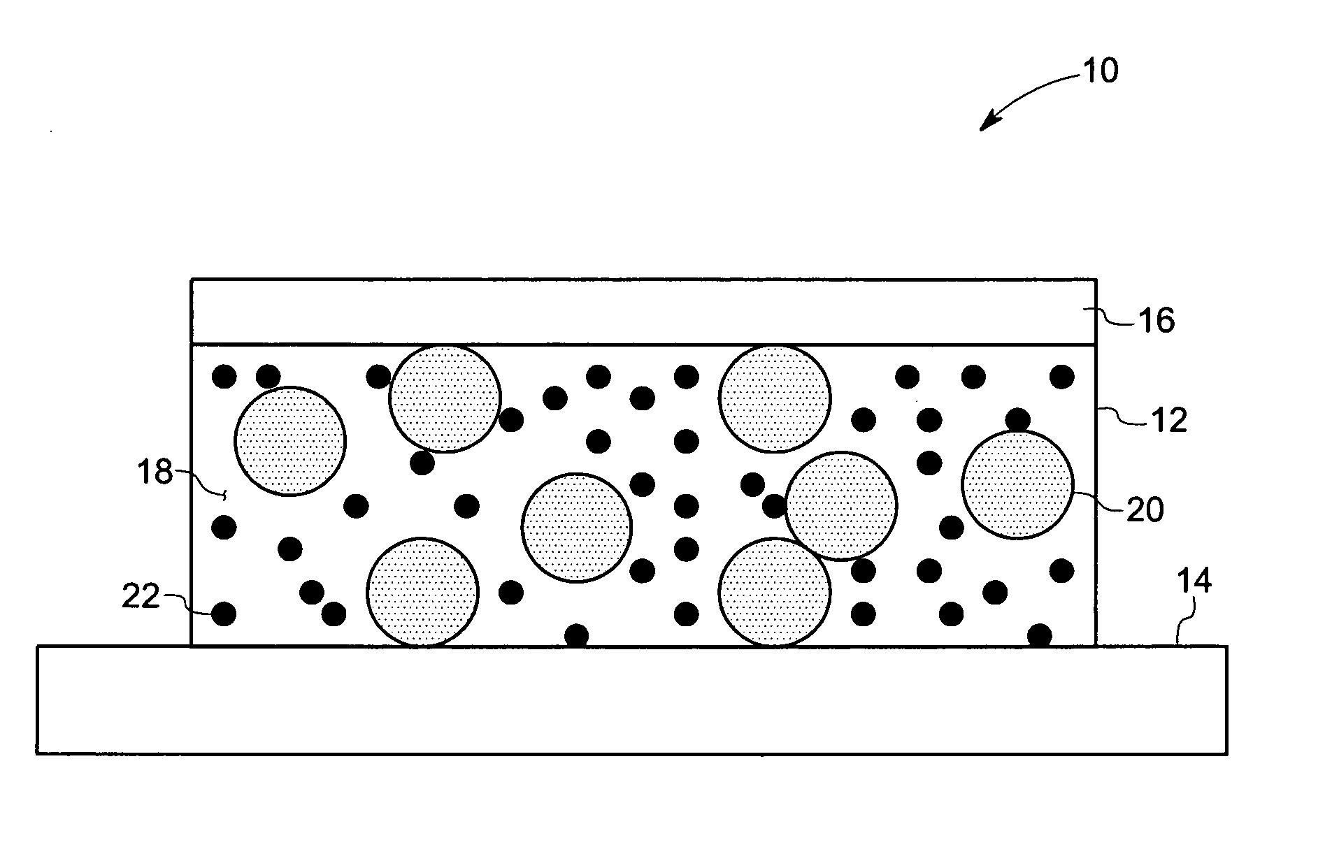
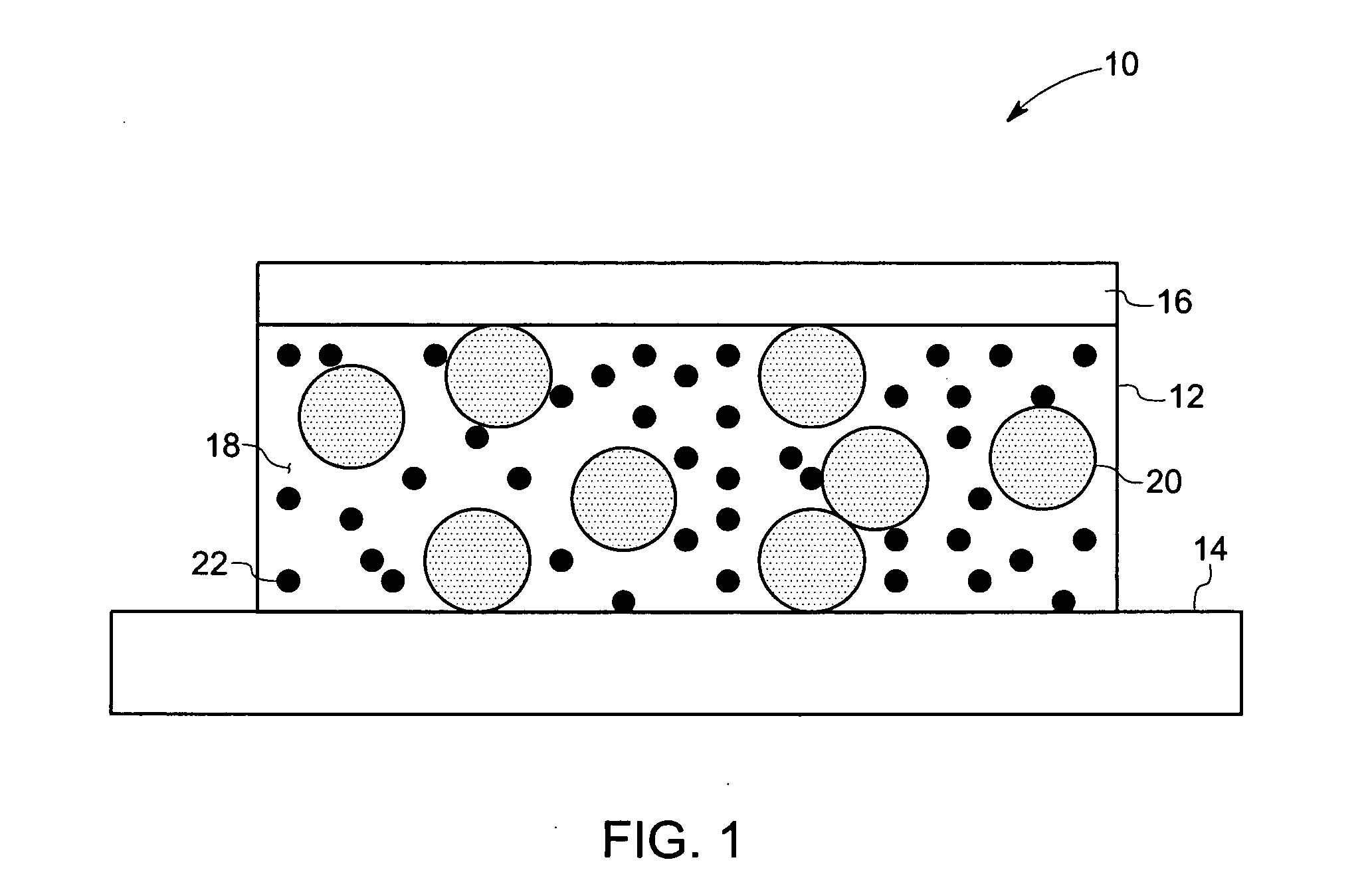
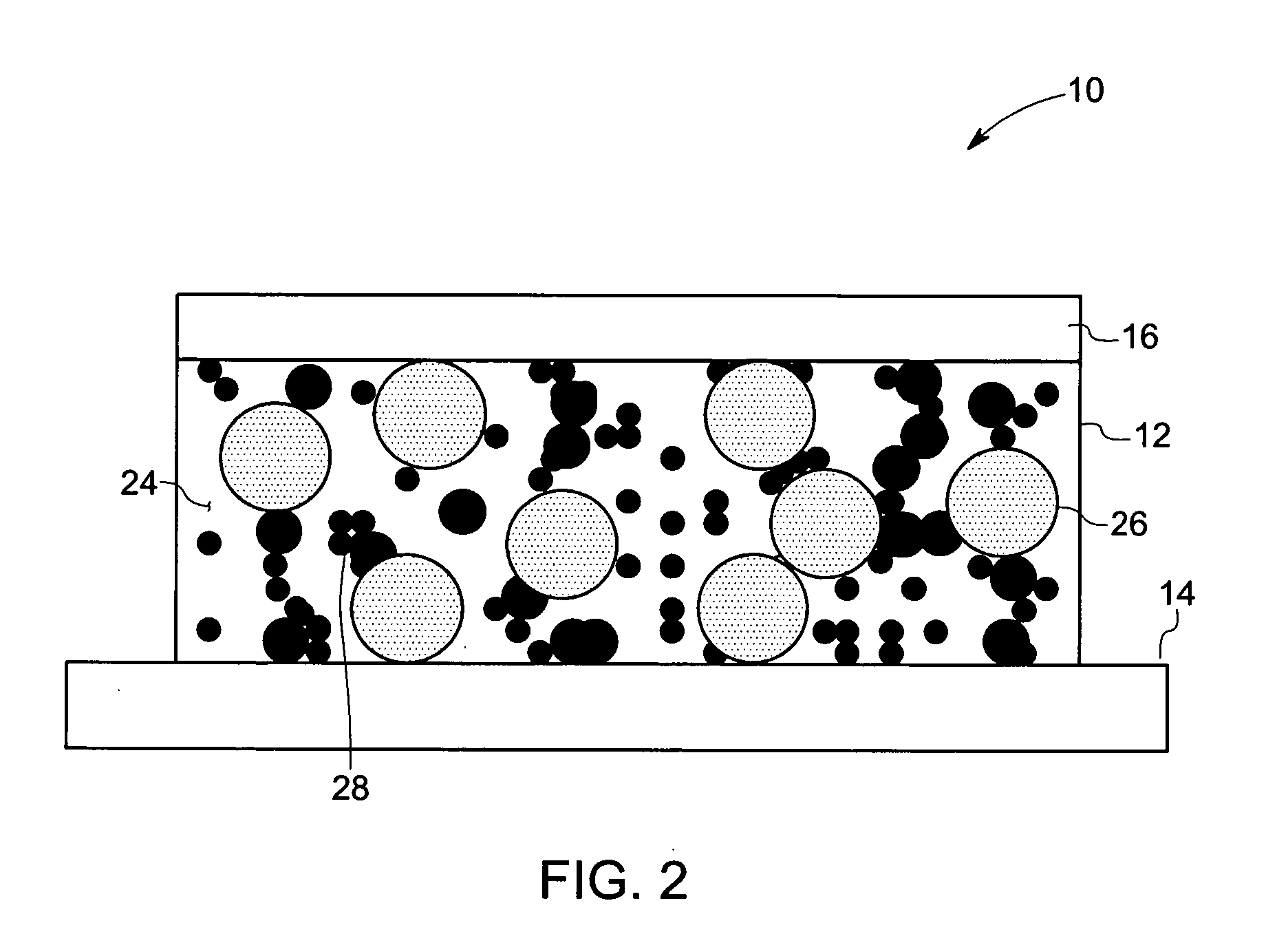
[0011] In accordance with an exemplary embodiment of the present invention, a method of making an adhesive composition is presented. The method includes contacting a curable low modulus elastomer with nano-sized metal particles and micron-sized metal particles

Problems solved by technology

The use of lead-free solder alloys, however, creates a new challenge for the reliable assembly of microelectronics components.
Unfortunately, the higher processing temperatures of lead-free alloy solders commonly exceed the design temperature of many circuit board materials.
Thus, incorporation of lead-free solders may not be feasible in certain applications and / or may lead to higher material costs where more expensive circuit board materials having higher design temperatures are utilized.
Further, such an increase in processing temperatures can lead to increases in thermal stresses on the components being connected and hence reduced robustness.
Moreover, increased processing temperatures generally increase energy consumption / costs in the fabrication of circuit boards and other devices.
While conductive adhesives having conductive fillers may have potential advantages in electrical conduction applications, they may also pose challenges, such as the relatively low electrical conductivity of the polymeric portion of the adhesive.
Moreover, a particular challenge with filled composites (e.g., metal-filled) is implementing the appropriate balance of filler loading, adhesive strength, and electrical conductivity.
For example, as filler loading is increased in an effort to advance electrical conductivity, the composite's adhesion may suffer, thereby reducing or limiting the conductivity.
Furthermore, conduction between filler particles in a composite is generally limited to filler-filler point contacts.
Indeed, properties of the interface between metallic fillers may contribute to degradation of the electrical properties of the polymer composites.
The fine particles, however, create more interfaces between the particles because of their larger surface area, further contributing to the degradation of electrical conductivity and thus making use of fine particles less beneficial.

Method used


Image

  • Electrically conductive adhesives
  • Electrically conductive adhesives
  • Electrically conductive adhesives

Examples


example 1

[0054]

Component-TypeGramsVinyl polymer-MviD150Mvi0.819Silicone hydride-MD50DH50M0.145Nanosilver0Micron Silver filler7.33Property (units)MeasurementViscosity (P) @ 20 rpm10.4Settling timeWithin 24 hrs

example 2

[0055]

Component-TypeGramsVinyl polymer-MviD150Mvi0.819Silicone hydride-MD50DH50M0.145Nanosilver0.4Micron Silver filler6.5Property (units)MeasurementViscosity (P) @ 20 rpm10Settling timeWithin 24 hrs

example 3

[0056]

Component-TypeGramsVinyl polymer-MviD150Mvi0.819Silicone hydride-MD50DH50M0.145Nanosilver0.8Micron Silver filler6.3Property (units)MeasurementViscosity (P) @ 20 rpm21.3Settling timeWithin 7 days


PUM

PropertyMeasurementUnit
Temperatureaaaaaaaaaa
Percent by massaaaaaaaaaa

Abstract

The present invention provides an electrically conductive adhesive composition having cured low modulus elastomer and metallurgically-bonded micron-sized metal particles and nano-sized metal particles. The low modulus elastomer provides the mechanical robustness and reliability by relieving the stresses generated; and the metallurgically-bonded micron-sized metal particles and nano-sized metal particles provide a continuous conducting path with minimized interface resistance. Addition of nano-sized metal particles lowers the fusion temperature and allows the metallurgical-bonding to occur at manageable temperatures.

Description

BACKGROUND [0001] The invention relates generally to electrically conductive adhesives and more specifically to such adhesives having a cured low modulus elastomer and metallurgically-bonded nano-sized metal particles and micron-sized metal particles. [0002] Reliable performance of electronic devices depends on the integrity and adhesion of the microelectronic components contained therein. Incorporating multiple components into a device creates several adhesive interfaces, interconnections, bonds, and so on, robustness of which is typically important for survival of the device during assembly and for reliability of the device during its subsequent service life. Adhesive interfaces, bonds, and connections, and the like, within electronic components are currently subjected to increasingly stringent selection requirements. [0003] For example, environmental concerns have resulted in a worldwide mandate to remove lead from all aspects of the microelectronic assembly process. The use of l...

Claims


Application Information

Patent Timeline
IPC IPC(8): H01B1/12
CPCB82Y30/00C08K3/08C08K2201/011C09J9/02C09J11/04C09J183/04C09J2483/00H01B1/22H05K3/321H05K2201/0133H05K2201/0257H05K2201/0266H05K2201/0272C08L83/00C08L2666/54
Inventor SIMONE, DAVIDE LOUISANGELIU, THOMAS MARTINTONAPI, SANDEEP SHRIKANTGIBSON, DAVID ALEXANDERZHANG, JIAN
Owner GENERAL ELECTRIC CO
Learn More