Current controlled switching mode power supply

a power supply and switching mode technology, applied in the direction of power conversion systems, dc-dc conversion, instruments, etc., can solve the problems of high voltage system problems, and high voltage system problems

Active Publication Date: 2007-06-14
SEMICON COMPONENTS IND LLC
View PDF4 Cites 25 Cited by
  • Summary
  • Abstract
  • Description
  • Claims
  • Application Information

AI Technical Summary

Benefits of technology

[0016] In some embodiments a switching mode power supply includes a switching device; a PWM unit for controlling on/off operations of the switching device by comparing a feedback voltage from a soft start unit or a voltage output unit with a sensing voltage of a switching sensing resistor, in series with the switching device; and an over-voltage controller for comparing the switching sensing voltage with a threshold voltage to generate a first output voltage, comparing the first output voltage with an output si

Problems solved by technology

If the MOSFET sensing current becomes excessive, the voltage provided on the MOSFET becomes excessive over the inherent voltage limit of the MOSFET when the MOSFET is off.
The MOSFET acting as the switching device is very likely to be broken down due to the e

Method used


Image

  • Current controlled switching mode power supply
  • Current controlled switching mode power supply
  • Current controlled switching mode power supply

Examples


Embodiment Construction

[0025] In the following, description of well known elements will be omitted for clarity. It will be understood that when an element or block is referred to as being connected to another element or block, the connection can be direct or through intervening elements or blocks.

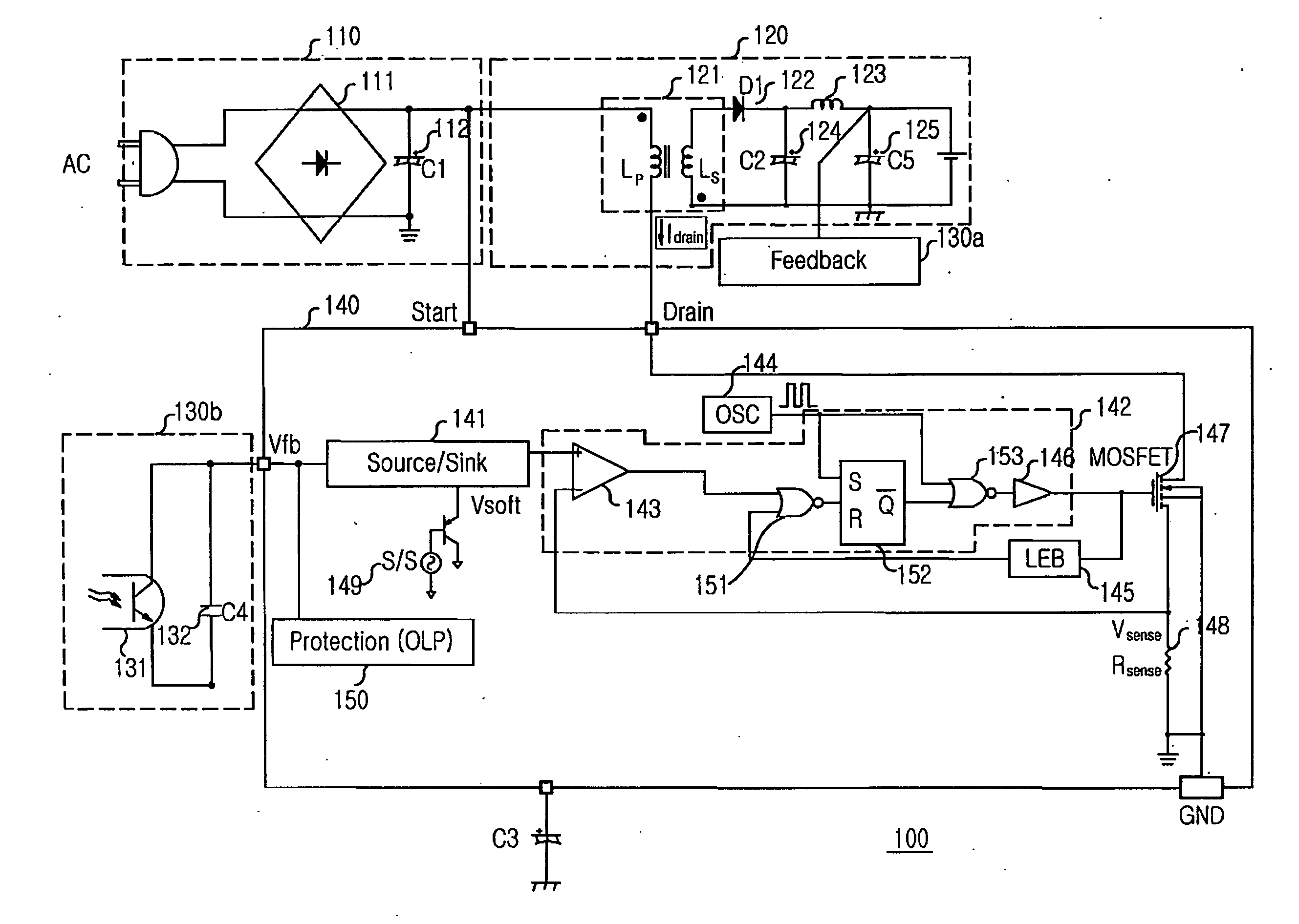
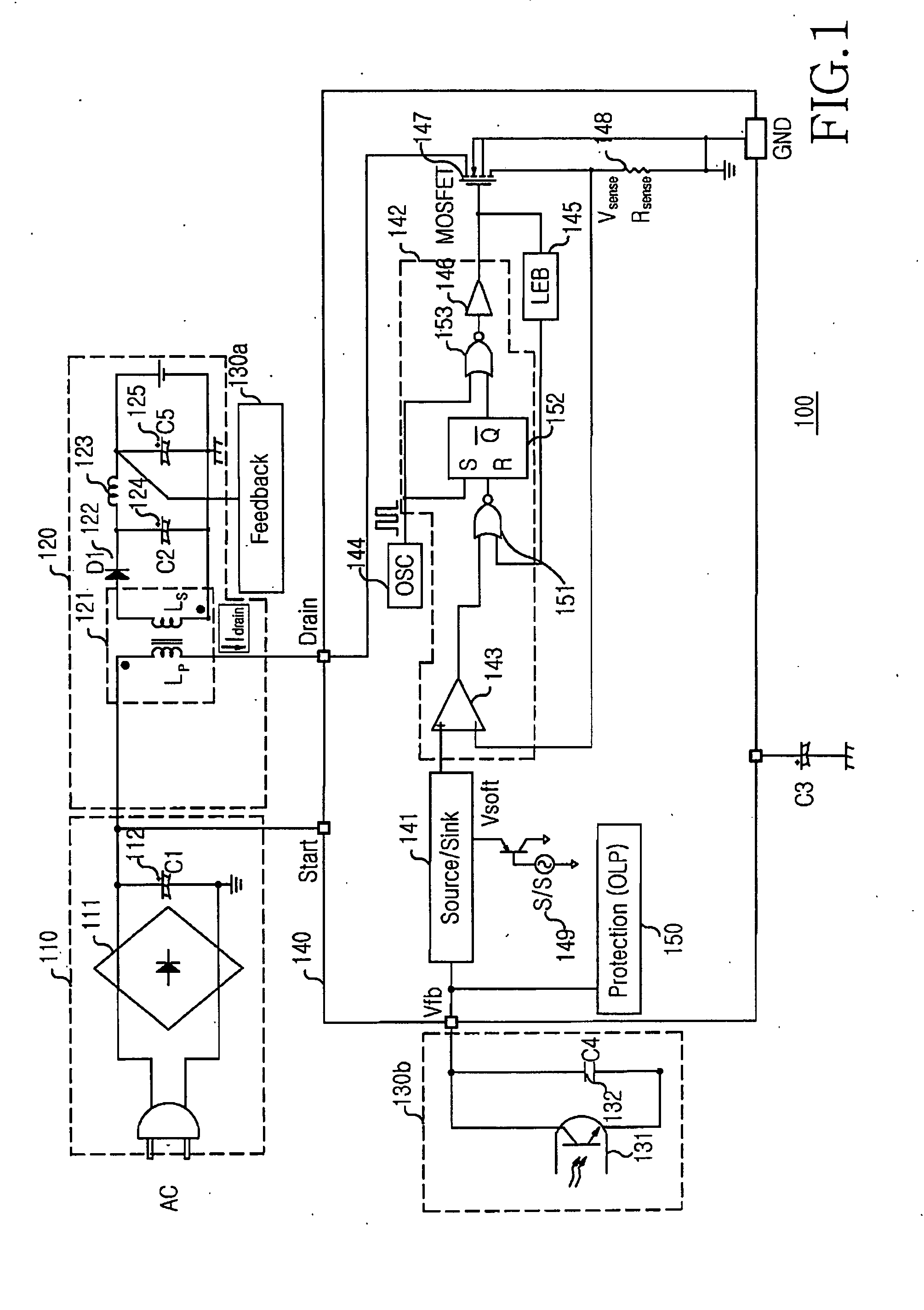
[0026]FIG. 3 is a circuit diagram of a switching controller 300 of a switching mode power supply according to an embodiment. The switching controller 300 may operate in connection of a DC voltage supply, a voltage output block, and a feedback circuit block, which can have the same structures as those of FIG. 1 or any one of their numerous equivalents. For this reason, these elements will not be shown here. Further, the elements to which no reference numerals or symbols are assigned can also have the same structures as those of FIG. 1, or any equivalent structure.

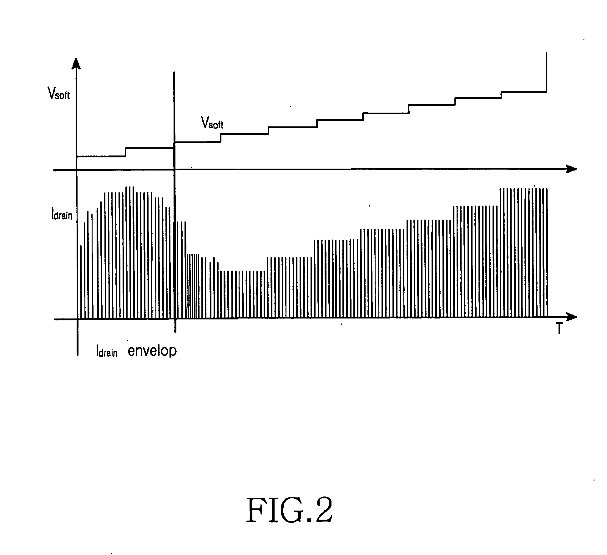
[0027]FIG. 3 illustrates a PWM unit which controls on / off operations of a switching device 330 by comparing a soft start voltage of a soft start unit o...


PUM


Abstract

A current controlled switching mode power supply is provided. A turn on/off time of a switching device is adjusted by controlling a leading edge blanking (LEB) time and an external drive current of the switching device by means of a switching controller, thus capable of preventing a switching current from being excessive due to a delay of a turn-off time of the switching device, which is caused by a circuit delay during a soft start of the switching mode power supply. Also, it is possible to prevent a switching current from being excessive due to a failure of accurately controlling a turn-off time of the switching device because of a delay caused when an output voltage (a voltage at a secondary winding of a transformer) of the switching mode power supply is designed to have a high voltage.

Description

CROSS REFERENCE TO RELATED APPLICATIONS [0001] This application claims priority under 35 U.S.C. § 119 to an application entitled “Current Controlled Switching Mode Power Supply” filed in the Korean Intellectual Property Office on Dec. 14, 2005 and assigned Ser. No. 2005-0122853, the contents of which are herein incorporated by reference in its entirety. BACKGROUND [0002] 1. Field of the Invention [0003] The present invention relates to a current controlled switching mode power supply, and more particularly, to an apparatus for adjusting a turn on / off time of a switching device by controlling a leading edge blanking (LEB) time and an external drive current of the switching device by means of a switching controller, thus capable of preventing a switching current from being excessive due to a delay of a turn-off time of the switching device, which is caused by a circuit delay during a soft start of the switching mode power supply. Also, the present invention can prevent a switching cur...

Claims


Application Information

Patent Timeline
IPC IPC(8): G05F1/00
CPCH02M1/32H02M1/36H02M3/33507H02M3/155
Inventor JANG, KYUNG-OUNHWANG, YOO-WOONG
Owner SEMICON COMPONENTS IND LLC
Why Eureka
Try Eureka