Class d amplifier

a class d amplifier and amplifier technology, applied in the direction of amplifiers with modulators/discharge tubes, amplifiers with semiconductor devices/discharge tubes, amplifier modifications to reduce noise influence, etc., can solve the problems of high-frequency distortion rapidly deteriorating the coil, new noise and distortion, and the kind of conventional class d amplifier. achieve the effect of simple and small-scale control circuits and reducing distortion

Inactive Publication Date: 2007-06-14
PANASONIC CORP
View PDF10 Cites 27 Cited by
  • Summary
  • Abstract
  • Description
  • Claims
  • Application Information

AI Technical Summary

Benefits of technology

[0021] It is therefore an object of the present invention to provide a class D amplifier that can reduce the distortion of a specific sampling frequency, the frequency of half of this frequency, and frequencies that are multiples of this frequency to a level where an LPF is not required even when an input value is a fixed value or a signal that slightly changes, and that can be implemented with a simple and small-scale control circuit.

Problems solved by technology

This high-frequency distortion rapidly deteriorates the coil that is the most fundamental and main component of the speaker section.
However, this kind of conventional class D amplifier has the following problems.
Further, in some cases, calculation errors due to re-sampling or fluctuation of the sampling frequency causes new noise and distortion in the class D amplifier itself, and, an analogue circuit including an operational amplifier, capacitor and resistor is required for generating a triangular wave which is a reference signal for generating a PWM signal.
Therefore, characteristic deterioration and increase in circuit scale cannot be avoided.

Method used


Image

  • Class d amplifier
  • Class d amplifier
  • Class d amplifier

Examples


embodiment 1

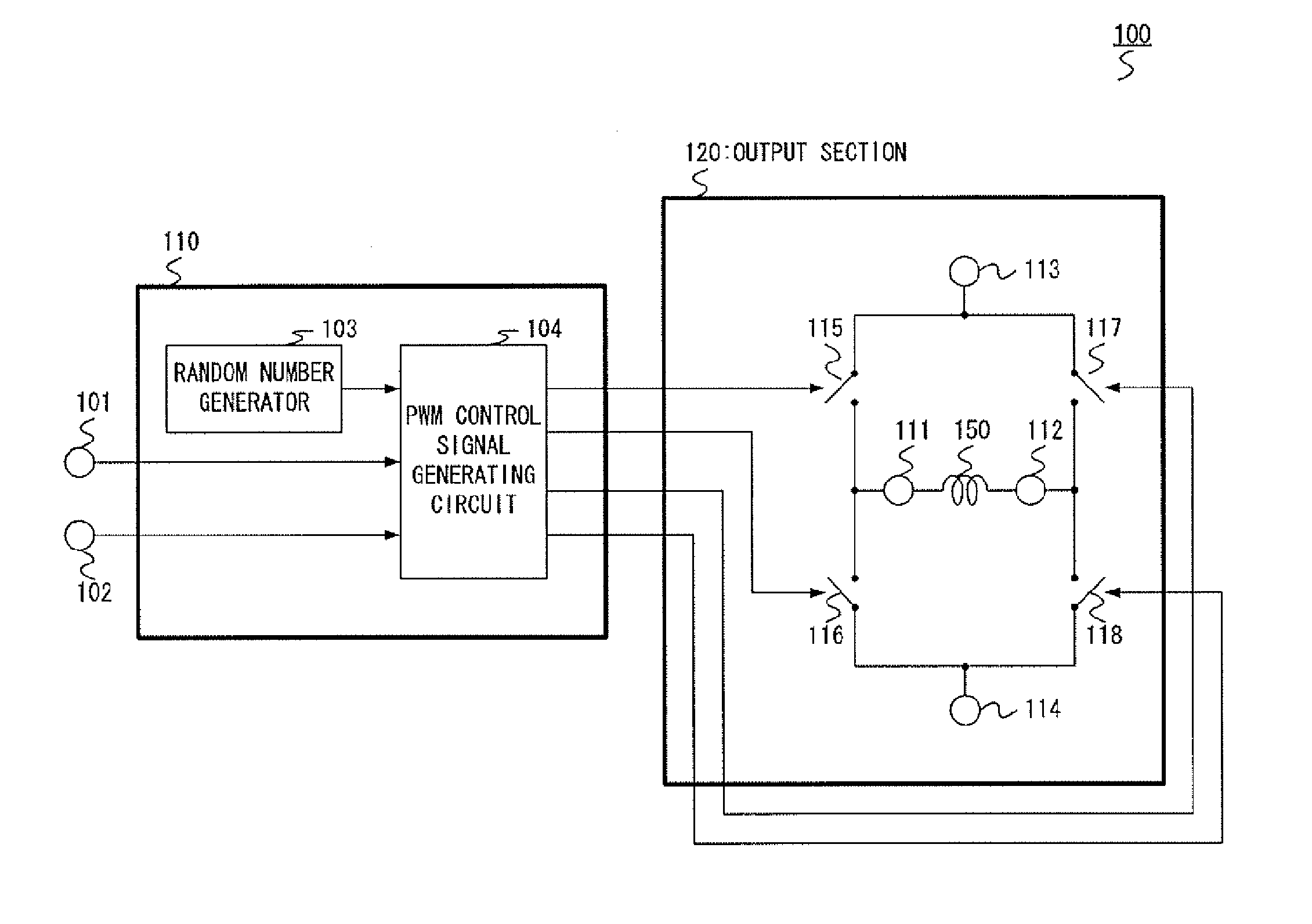
[0075]FIG. 1A-D is a circuit diagram showing a configuration of the class D amplifier according to Embodiment 1 of the present invention based on the above-described basic concepts. This embodiment is an example of application to a class D amplifier suitable for use in an audio that outputs a PWM signal to be supplied to an inductive load such as a speaker.

[0076] In FIG. 3, class D amplifier 100 is configured having: output control section 110 that is configured with input terminal 101, mute signal input terminal 102, random number generator 103 and PWM control signal generating circuit 104; and output section 120 that is configured with first and second output terminals 111 and 112 to which inductive load 150 such as a speaker is connected, first power supply terminal 113 that supplies a first potential, second power supply terminal 114 that supplies a second potential, first switch 115 that connects first power supply terminal 113 and first output terminal 111, second switch 116 ...

embodiment 2

[0109]FIG. 7 is a circuit diagram showing a configuration of the class D amplifier according to Embodiment 2 of the present invention. In the description of this embodiment, components that are the same as one in FIG. 3 are assigned the same reference numerals without further explanations.

[0110] In FIG. 7, class D amplifier 200 is configured having: output control section 210 that is configured with input terminal 101, mute signal input terminal 102, random number generator 103 and PWM control signal generating circuit 211; and output section 220 that is configured with first and second output terminals 111 and 112 to which inductive load 150 such as a speaker is connected, first power supply terminal 113 that supplies a first potential, second power supply terminal 114 that supplies a second potential, first PMOS transistor 221 that connects first power supply terminal 113 and first output terminal 111, first NMOS transistor 222 that connects first output terminal 111 and second p...

embodiment 3

[0142]FIG. 1 is a circuit diagram showing a configuration of the D class amplifier of Embodiment 3 of the present invention.

[0143] In the description of this embodiment, components that are the same as ones in FIG. 7 are assigned the same reference numerals without further explanations.

[0144] In FIG. 11, class D amplifier 300 is configured having: output control section 210 that is configured with input terminal 101, mute signal input terminal 102, random number generator 103 and PWM control signal generating circuit 211; and output section 320 that is configured with first and second output terminals 111 and 112 to which inductive load 150 such as a speaker is connected, first power supply terminal 113 that supplies a first potential, second power supply terminal 114 that supplies a second potential, first PMOS transistor 221 that connects first power supply terminal 113 and first output terminal 111, first NMCS transistor 222 that connects first output terminal 111 and second po...


PUM


Abstract

A class D amplifier is provided that is capable of reducing distortion of a specific sampling frequency, and frequencies that are multiples of this frequency to a level where an LPF is not required and small-scale control circuit. Class D amplifier 100 is provided with H (full) bridge output section 120, output control section 110 that is configured with random number generator 103 that takes individual random numbers that do not depend on input values as output values, and PWM control signal generating circuit 104 that generates a final PWM control signal from the input values and output values of random number generator 103. Output control section 110 divides a pulse signal outputted at a reference point between sampling frequencies into a plurality of pulse signals with random widths that do not include the reference point, and outputs the pulse signals with random widths.

Description

BACKGROUND OF THE INVENTION [0001] 1. Field of the Invention [0002] The present invention relates to a class D amplifier that operates using switching techniques, and more particular, to a class D amplifier suitable for use in audios that carry out power amplification of a PWM (Pulse Width Modulation) signal using switching operation corresponding to the PWM signal based on a speech signal etc. and supply the obtained output signal to a load including a speaker etc. [0003] 2. Description of the Related Art [0004] In a sound apparatus that amplifies a speech, supplies the signal to a speaker, and obtains speech corresponding to the speech signal from the speaker, various methods are adopted for amplification of the speech signal according to various purposes. In particular, there are improved methods for the case of obtaining an output signal for exciting the speaker based on the input speech signal. Regarding power amplification for speech signals, a class D amplifier that carries o...

Claims


Application Information

Patent Timeline
Patent Type & Authority Applications(United States)
IPC IPC(8): H03F3/38
CPCH03F1/26H03F1/32H03F3/2171H03F3/2173H03F2200/114H03F2200/351H03F2200/372H03F2200/456H03K17/162H03K17/6872H03K17/6874
Inventor MOCHIZUKI, KOUJI
Owner PANASONIC CORP
Why Eureka
Try Eureka